Layer structure and use thereof to form a ceramic layer structure between an interconnect and a cathode of a high-temperature fuel cell

A fuel cell, layer structure technology, applied in the field of layer structure, can solve the problems of thermal expansion performance, high conductivity, chromium diffusion and evaporation, etc.

Active Publication Date: 2013-11-20
PLANSEE SE +1
View PDF6 Cites 13 Cited by
  • Summary
  • Abstract
  • Description
  • Claims
  • Application Information

AI Technical Summary

Problems solved by technology

A problem with these materials is the formation of chromium(III) oxide on the surface of the interconnect at the junction under the high temperature, oxidizing atmosphere conditions that are applied in solid oxide fuel cells, especially on the cathode side (Cr 2 o 3 )film
Howeve

Method used


Image

  • Layer structure and use thereof to form a ceramic layer structure between an interconnect and a cathode of a high-temperature fuel cell
  • Layer structure and use thereof to form a ceramic layer structure between an interconnect and a cathode of a high-temperature fuel cell
  • Layer structure and use thereof to form a ceramic layer structure between an interconnect and a cathode of a high-temperature fuel cell

Examples


Embodiment 1

[0096] Composed of Cu 0.6 Ni 0.4 mn 2 o 4 30 g of spinel powder with an average particle size between 1.5 μm and 3.5 μm and a composition of La 0.75 Sr 0.2 mn 0.9 co 0.1 o 3-δ 1.935g of perovskite powder with an average particle size between 1.5μm and 3.5μm, and 1.520g of CuO, 0.9516g of NiO and 5.0283g of Mn 2 o 3 (sintering aid) mixed in ethanol solution and subsequently homogenized on table rollers or in a planetary ball mill. The homogeneous powder is dried and subsequently sieved. The sifted powder is mixed with a solvent containing terpineol, to which ethyl cellulose has been previously added as a binder, and subsequently homogenized on a three-piece roller, resulting in a highly viscous, flowable slurry . The paste is applied to at least the contact web (the contact surface that conducts current) of the connector 2 by thick film techniques such as screen printing or mask printing or roll coating. However, a complete coating of the connecting body 2 is advant...

Embodiment 2

[0100] La 0.75 Sr 0.2 MnO 3-x 、Cu 0.6 Ni 0.4 mn 2 o 4 and metal oxides (CuO, Mn 2 o 3 , NiO, Co 3 o 4 ) were used as the initial material. For the manufacture of the first sub-layer 4 with the composition Cu 0.6 Ni 0.4 mn 2 o 4 30g of spinel powder with an average particle size between 1.5μm and 3.5μm, 1.008g of CuO, 0.631g of NiO and 2.2347g of Mn 2 o 3 Mixing in ethanol solution followed by homogenization on table rollers or in a planetary ball mill. The homogenized powder is dried and subsequently sieved. The sifted powder is mixed with a solvent containing terpineol, to which ethyl cellulose has been previously added as a binder, and subsequently homogenized on a three-piece roller, resulting in a highly viscous, flowable slurry . The paste is applied to the gas connection plate of the connector 2 by thick film techniques such as screen printing or mask printing or roll coating. However, a complete coating of the connecting body 2 is advantageous, wherei...


PUM

PropertyMeasurementUnit
Average particle sizeaaaaaaaaaa
Particle sizeaaaaaaaaaa

Abstract

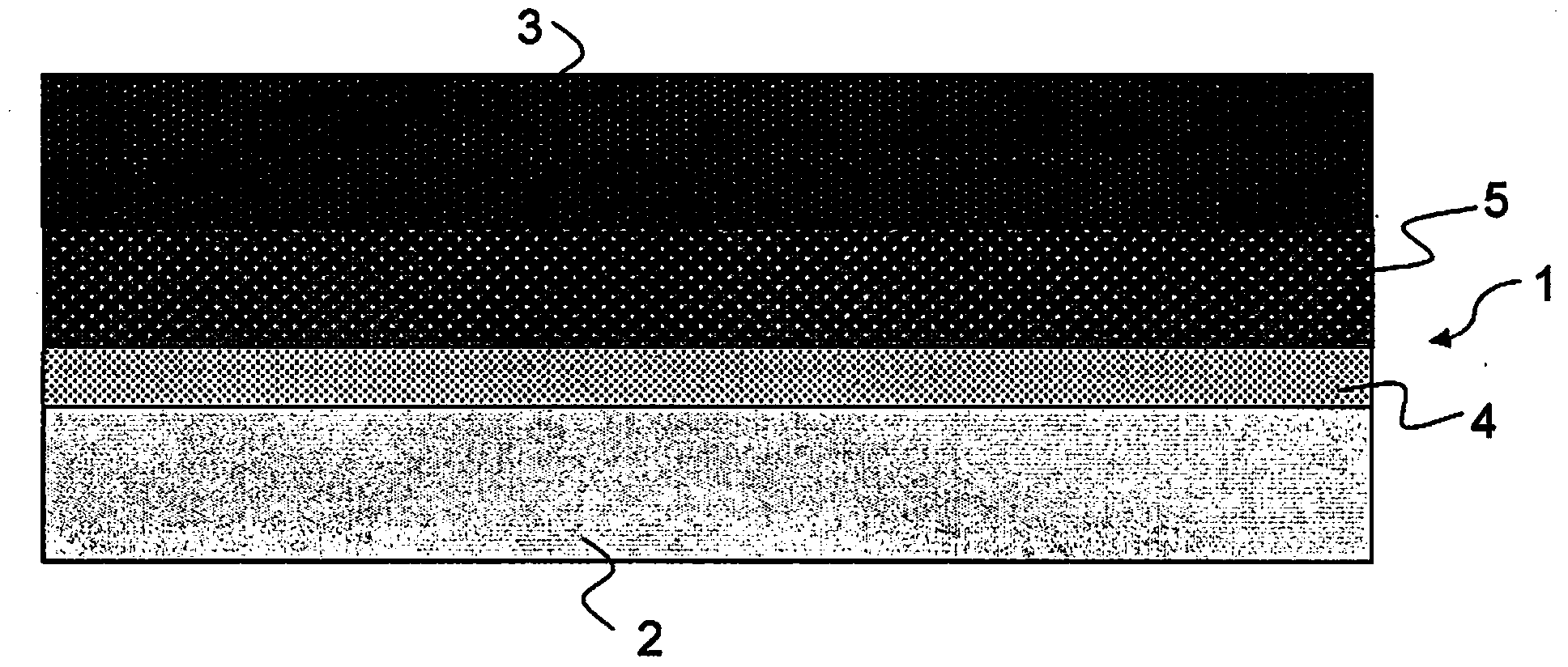
The invention relates to a layer structure that is formed between an interconnect and a cathode of a high-temperature fuel cell and that can be used to form a ceramic layer structure between an interconnect and a cathode. The interconnect is made of a metal alloy containing chromium. The aim of the invention is to provide a layer structure between an interconnect and a cathode of a high-temperature fuel cell, by means of which good protective function (against corrosion and against chromium evaporation), high electrical conductivity, and good thermal expansion behavior matched to the materials of an interconnect and of a cathode can be achieved. The layer structure is formed in the green state by a powdery spinel and at least one metal oxide from the group comprising CuO, NiO, CoOx, and MnOx as a sintering additive, and at least one powdery perovskite. Chromium is not contained in any of said chemical compounds. The fraction of contained spinel having the metal oxides as a sintering additive is reduced from the side facing the interconnect to the side facing the cathode, and the fraction of perovskite is reduced from the side facing the cathode to the side facing the interconnect.

Description

technical field [0001] The present invention relates to a layer structure formed between an interconnect and a cathode of a high temperature fuel cell and which can be used to form a ceramic layer structure between the interconnect and the cathode. Background technique [0002] High-temperature fuel cells (Solid Oxide Fuel Cells, or SOFCs) allow the direct conversion of chemical energy into electrical energy. The main functional unit of this type of solid oxide fuel cell is the cathode-electrolyte-anode unit (single cell). A solid oxide fuel cell has two electrodes: a cathode and an anode separated from each other by an oxygen-conducting electrolyte (a solid). During operation of such a single cell, the anode is supplied with fuel (such as H 2 、CH 4 , CO, etc.), supplying the oxidant (e.g., O 2 , air, etc.). At operating temperatures in the range of 650°C to 1000°C, oxygen ions are conducted from the cathode side through the oxygen conducting electrolyte to the anode wh...

Claims


Application Information

Patent Timeline
IPC IPC(8): H01M8/02H01M8/12C23C24/10B32B18/00C04B35/01C01G45/00C01G53/00
CPCH01M8/0217C04B2235/3281C04B2235/768C04B2235/3265H01M8/0236Y02E60/50C04B35/016C04B2235/79C04B2235/80C04B2235/3213C04B2235/3279C04B2235/763C04B35/01C04B2237/34H01M2008/1293H01M8/0228C23C24/08C23C28/04H01M8/021C04B2235/3227C04B2235/786C04B2235/5436Y02E60/525B32B18/00C04B2235/3275C01G45/00C01G53/00C23C24/10H01M8/02H01M8/12
Inventor 马尔科·布兰德奈尔约翰内斯·施密德安德里亚斯·温斯库图尼斯尼古拉·特卢费门库维克塔·萨乌丘克米海勒斯·库斯奈佐夫卡林·洛克亚历山大·米凯利斯
Owner PLANSEE SE
Why Eureka
Try Eureka