
Device and method for calibrating optical fiber scanning light source wavelength based on gas absorption spectral lines

A technology of optical fiber scanning and gas absorption, which is applied in the field of optical fiber communication and sensing, can solve the problems of unfavorable calibration device miniaturization, modularization, unfavorable application system integration, and large volume of spectrometer, so as to achieve real-time calibration and precise positioning, strong The effect of scalability and broad market prospects

Active Publication Date: 2013-11-27
TIANJIN UNIV
View PDF4 Cites 29 Cited by
  • Summary
  • Abstract
  • Description
  • Claims
  • Application Information

AI Technical Summary

Problems solved by technology

The spectrometer is large and expensive, which is not conducive to the miniaturization and modularization of the calibration device, and is also not conducive to the integration with the application system; although the FBG array and the F-P etalon can provide multiple reference wavelengths for calibration, they are limited by the thermal stability of the device. The reference wavelength will drift to different degrees with the change of temperature, thus deviating from its nominal value and bringing errors to the calibration

Method used

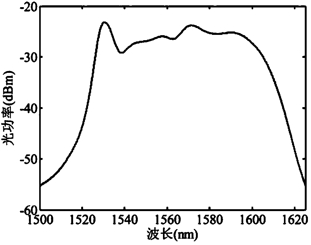

Image

  • Device and method for calibrating optical fiber scanning light source wavelength based on gas absorption spectral lines
  • Device and method for calibrating optical fiber scanning light source wavelength based on gas absorption spectral lines
  • Device and method for calibrating optical fiber scanning light source wavelength based on gas absorption spectral lines

Examples


Embodiment 1

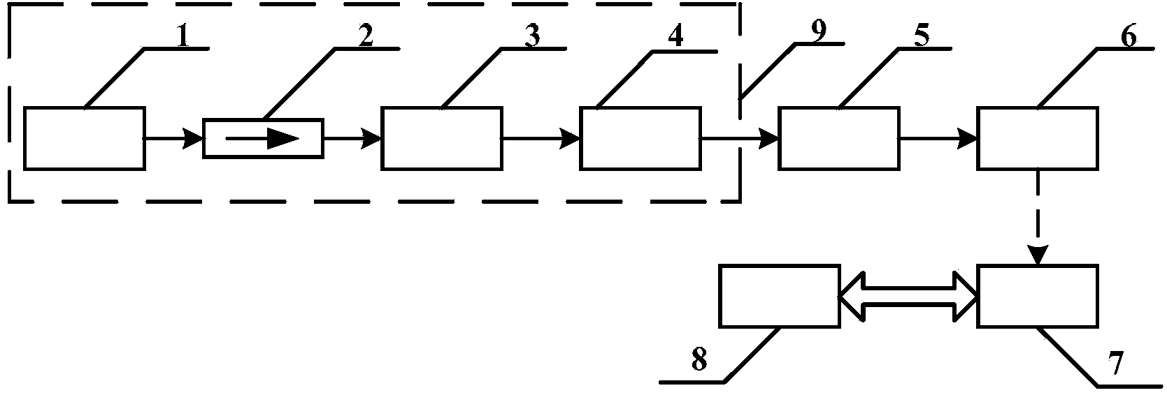
[0037] like figure 1 As shown, the optical fiber scanning light source wavelength calibration device based on gas absorption lines in the present invention includes a fiber scanning light source 9 , a gas chamber 5 , a detector 6 , a data acquisition card 7 and a computer 8 .

[0038] The optical fiber scanning light source 9 is composed of a broadband light source 1 , an isolator 2 , an adjustable attenuator 3 and a fiber optic Fab filter 4 arranged in sequence. Broadband light source 1, isolator 2, adjustable attenuator 3, fiber optic Fab filter 4, gas chamber 5, and detector 6 are connected in sequence through FC / APC single-mode fiber adapter, between detector 6 and data acquisition card 7 Connected by copper wires, the data acquisition card 7 and the computer 8 realize data communication through the USB interface.

[0039] The light emitted by the broadband light source 1 passes through the isolator 2 and the adjustable attenuator 3 and then enters the continuous voltage-...

Embodiment 2

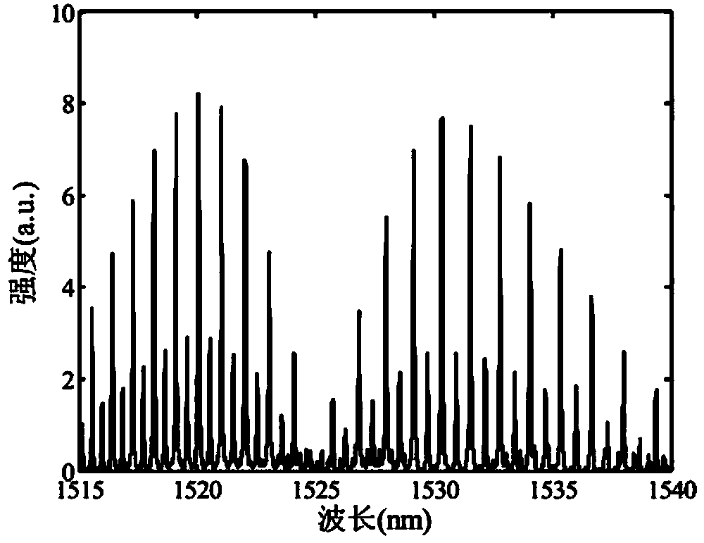
[0048] Acetylene is a gas that has a strong absorption of near-infrared light, and there are dozens of strong absorption lines between 1515nm and 1540nm, such as image 3 shown. Taking acetylene as an example, the wavelength calibration method of the optical fiber scanning light source 9 is described. In the actual calibration process, it is not necessary to collect all the absorption lines of the gas, and the local absorption spectrum can provide enough reference wavelengths for calibration. Figure 4 The gas absorption spectrum collected by the detector 6 is given when the driving voltage of the optical fiber scanning light source 9 varies between 6.6V and 9.6V, and the calibration gas is acetylene-nitrogen mixed gas, and the volume ratio of acetylene is 30%. The second-order derivative peak-seeking method is used for peak detection on the spectral curve. The driving voltage at the maximum value of the second-order derivative roughly corresponds to the central absorption wa...

Embodiment 3

[0052] The method described in the present invention is simple and easy to implement, the required calibration device is compact in structure, and is easy to integrate with other optical fiber sensing systems, so that the present invention can be used not only for offline calibration of the output wavelength of the scanning light source, but also for online real-time measurement of the optical wavelength. This embodiment 3 is an application expansion implementation of the present invention, Figure 8 An integration scheme of the fiber scanning light source calibration system and the fiber grating temperature measurement system is given. It includes a fiber scanning light source 9 composed of a broadband light source 1, an isolator 2, an adjustable attenuator 3 and a fiber Fap filter 4. The narrow linewidth scanning light output by the fiber Fap filter 4 is split into two by a 3dB coupler 10 A branch, 50% of the light enters the gas chamber 5 and the first photodetector 13 in t...


PUM


Abstract

The invention discloses a device and method for calibrating an optical fiber scanning light source wavelength based on gas absorption spectral lines. The device and method are suitable for the precise locating of a scanning light source output wavelength based on an F-P filter in the field of optical fiber communication and sensing. The device and method provide multiple reference wavelengths for the wavelength calibration of an optical fiber scanning light source by utilizing the multiple absorption spectral lines of gas molecules in a near-infrared wave band, and are high in stability. In the calibration process, broadband light passes through the F-P filter driven by continuous voltages, outputs narrow-linewidth scanning light, and interacts with the gas molecules in a gas chamber to form gas absorption spectrums. Through base line extraction, absorption peak fitting and absorption wavelength query, the driving voltage and the absorption wavelength corresponding to each absorption spectral line of the gas are obtained. According to the voltage-wavelength corresponding relation of each spectral line, calibration is carried out on the output wavelength of the optical fiber scanning light source, and system wavelength locating is carried out through spline interpolation. The device and method have the advantages of being simple in device, easy to integrate, high in precision and the like, and have wide application prospects.

Description

technical field [0001] The invention relates to the field of optical fiber communication and sensing, in particular to a method for calibrating the output wavelength of a scanning light source with an optical fiber F-Perot tunable filter as a key component. Background technique [0002] As a tunable narrow-linewidth light source, fiber-optic scanning light source has developed rapidly in recent years due to its advantages of wide output wavelength range and narrow output spectral linewidth, and is widely used as a light source for various optical fiber communication and sensing systems . Compared with frequency-selective devices such as FBG and M-Z interferometer, the fiber-optic F-P tunable filter has a wide tuning range, fast tuning speed, high resolution and fineness, and is a common device for forming a fiber-optic scanning light source. The Fap filter is based on the principle of the Fap interferometer for wavelength selection. When a beam of broadband light is inciden...

Claims


Application Information

Patent Timeline
IPC IPC(8): G01J9/00G01N21/35
Inventor 刘琨刘铁根俞琳江俊峰宋璐瑶孟云霞王涛汪冉冉王立恒
Owner TIANJIN UNIV
Learn More