Heat radiation device with pulsating flow and leaf vein type micro channel

A technology of heat dissipation device and micro flow channel, which is applied in indirect heat exchangers, lighting and heating equipment, cooling/ventilation/heating renovation, etc. problem, to achieve the effect of good heat dissipation, strengthening the transmission of heat energy, and prolonging the time of continuous effective heat dissipation

Inactive Publication Date: 2013-12-11
UNIV OF ELECTRONICS SCI & TECH OF CHINA
View PDF3 Cites 13 Cited by
  • Summary
  • Abstract
  • Description
  • Claims
  • Application Information

AI Technical Summary

Problems solved by technology

[0005] ⑴The heat sink cold plate simply connects the micro-channels in parallel, and the fluid entering each channel will cause a large pressure loss, which not only loses power, but also leads to different flow rates entering each channel, and the heat dissipation effect is not ideal; There may even be partial reflux ( figure 1 The phenomenon indicated by the arrow in 9-1.3) leads to poor heat dissipation in local areas, and in severe cases, it will cause damage to components;
[0006] (2) The heat sink cold plate simply uses a micropump to transport fluid into the flow channel. The heat transfer effect of the fluid is poor, and it can only dissipate heat passively. This type of heat sink cold plate generally has a maximum temperature area of ​​43°C and a minimum temperature area of ​​36°C. The temperature difference between the high and low temperature areas is about 7°C, and there is an obvious heat concentration effect at the edge

Method used


Image

  • Heat radiation device with pulsating flow and leaf vein type micro channel
  • Heat radiation device with pulsating flow and leaf vein type micro channel
  • Heat radiation device with pulsating flow and leaf vein type micro channel

Examples


Embodiment 1

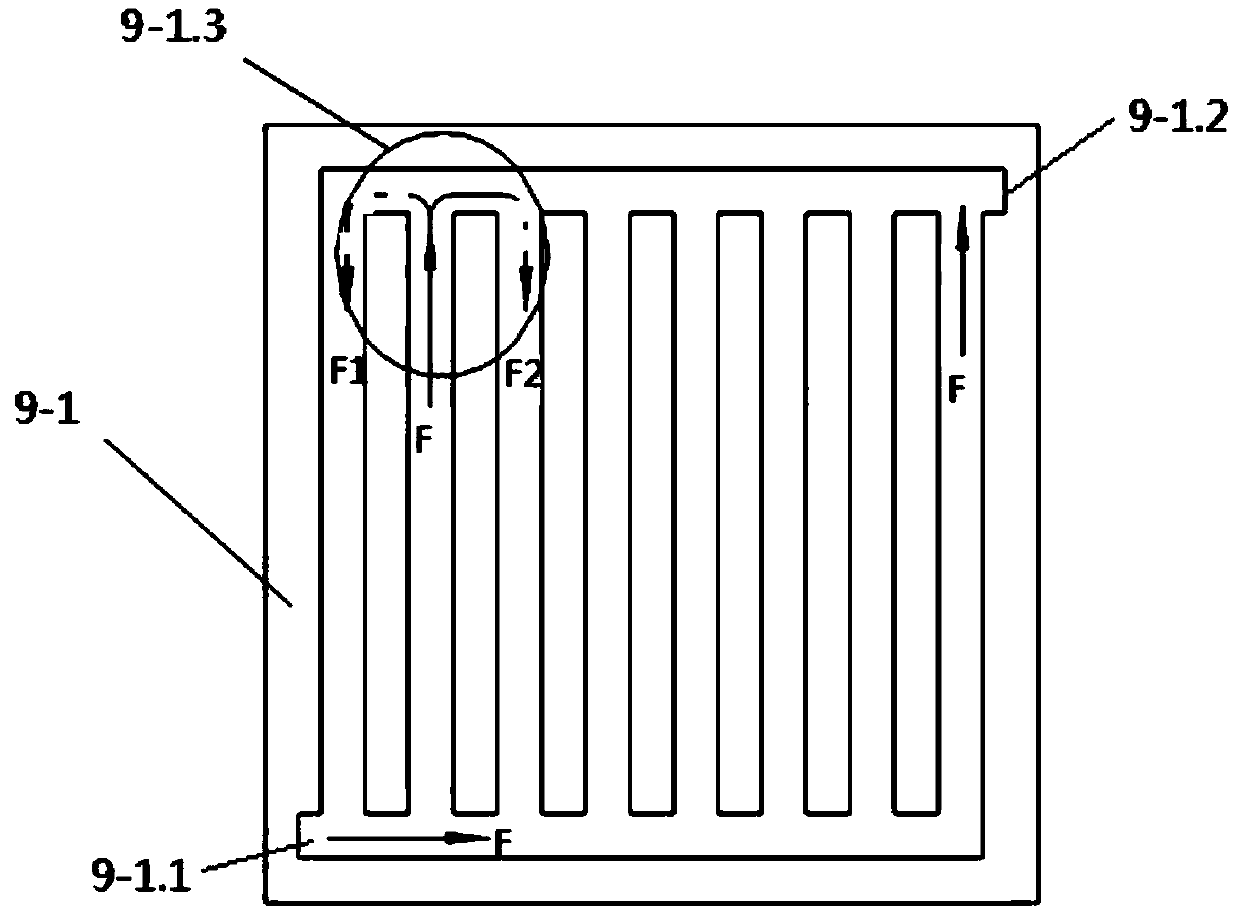
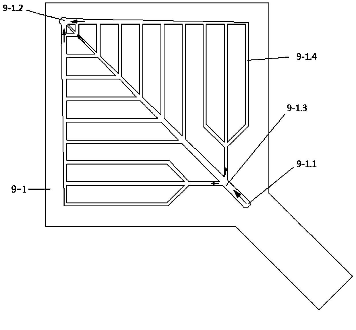
[0022]Embodiment 1: The radiator 9 in this embodiment is composed of a microchannel substrate 9-1 and a (radiator) cover plate 9-2. The main body of the microchannel heat dissipation substrate 9-1 (length×width×thickness) is 100×100× 3.0mm, the depth of each flow channel is 2mm, the size of the handle is (length×width×thickness) 50×20×3.0mm, and the total heat dissipation area is 5357.7042mm 2 , wherein: main channel 9-1.3 long? , The width of the water inlet is 3.54mm, and the width of the water outlet is 0.5mm. The width of each branch channel 9-1.4 is 1.5mm. The length of the branch channel is 51.3mm, the length of the third branch channel is 42.1mm, the length of the fourth level branch channel is 32.8mm, the length of the fifth level branch channel is 23.5mm, the length of the sixth level branch channel is 14.2mm, and the seventh level branch channel The length of the channel is 4.8mm, and the branch channels at all levels are symmetrically arranged on both sides of the ...

Embodiment 2

[0026] The main body and pulsating flow generation system of the microchannel substrate 9-1 in this embodiment are the same as those in Embodiment 1, and the structure of the microchannel cooling plate 9-3 is also the same as that of the microchannel substrate 9-1. Each branch channel (leaf vein) 9-3.4 on the heat dissipation plate 9-3 is provided with (upper and lower branch channel) communication ports 9-3.5 as the cooling medium (water) inlet and the corresponding branch flow on the vein-type micro-channel heat dissipation substrate The outer end of the road 9-1.4 is connected, and the cooling medium outlet 9-3.2 on the vein type microchannel cooling plate 9-3 is located on the main channel 9-3.3 of the vein type microchannel cooling plate shank (i.e. the main channel 9 -3.3 wide mouth end) and communicate with the cooling medium outlet 9-2.2 on the radiator cover plate; the cooling water (medium) in this embodiment is passed through the micro-channel substrate by the coolin...


PUM


Abstract

The invention discloses a heat radiation device with a pulsating flow and a leaf vein type micro channel. The heat radiation device is used in cooperation with an electronic element, and comprises a heat radiator, a pulsating flow generation system and a solenoid valve controller. The heat radiator comprises a micro channel heat radiation substrate or a micro channel heat radiation plate with the leaf vein type micro channel, and a cover board. The pulsating flow generation system comprises a motor, a piston type hydraulic cylinder, two liquid inlet solenoid valves and two liquid outlet solenoid valves, wherein a pair of liquid inlets and a pair of liquid outlets are formed in the front end and the rear end of a cylinder body of the piston type hydraulic cylinder respectively, the two liquid inlet solenoid valves are correspondingly connected with the two liquid inlets of the hydraulic cylinder, and the two liquid outlet solenoid valves are correspondingly connected with the two liquid outlets of the hydraulic cylinder. The solenoid valve controller comprises a signal emitter and a signal receiver. The forward travel and the back travel of the piston type hydraulic cylinder can both provide a continuous pulsating cooling medium flow for the heat radiator, the continuous and effective heat radiation time of a heat radiation cooling plate is prolonged, the mutual disturbance and mixing of a cooling medium in the micro channel are obviously strengthened, and a heat boundary layer is damaged. Therefore, the heat radiation device with the pulsating flow and the leaf vein type micro channel has the advantages of being good in heat radiation effect, high in heat radiation efficiency, good in temperature uniformity in a heat radiation area, high in reliability and stability of work of elements and the like.

Description

technical field [0001] The invention relates to a cooling device for supporting electronic components, in particular to a pulsating cooling liquid flow generated by a pulsating flow generation system to provide to the blade-type micro-channel heat sink cold plate, so as to provide high power consumption (high heat flux density) electronic components Heat dissipation treatment is carried out during work to ensure the reliable operation of electronic components and extend their service life. Background technique [0002] When electronic components work, due to power loss, the temperature of the device itself rises. When the temperature cannot be conducted or convected in time, it will cause the internal temperature of the device itself to rise and affect its performance, reducing its working stability and reliability. The higher the power consumption of electronic components, the higher the heat generated, and the high-density packaging distributes the heat on a smaller surfac...

Claims


Application Information

Patent Timeline
Patent Type & Authority Applications(China)
IPC IPC(8): H01L23/473H05K7/20
CPCF28D15/0233F28D15/0266
Inventor 徐尚龙汪超秦杰梁涛
Owner UNIV OF ELECTRONICS SCI & TECH OF CHINA
Why Eureka
Try Eureka