Carbon nanotube air filtering material with gradient structure and preparation method thereof

A technology of air filter materials and carbon nanotubes, applied in the direction of filtration separation, separation methods, chemical instruments and methods, etc., can solve the problems of unfavorable use of carbon nanotube membranes, low mechanical strength of carbon nanometer membranes, high filtration resistance, etc., and achieve Good industrial application prospects, long service life, and the effect of long service life

Active Publication Date: 2013-12-18
TSINGHUA UNIV
View PDF2 Cites 21 Cited by
  • Summary
  • Abstract
  • Description
  • Claims
  • Application Information

AI Technical Summary

Problems solved by technology

However, how to reflect the excellent properties of carbon nanotubes at the nanoscale at the macroscale is still a challenge
The technical challenge is to keep carbon nanotubes with sufficient mechanical strength on a macroscopic scale to meet the requirements for use in air filtration; on the other hand, the macroscopic body composed of carbon nanotubes also needs to have sufficient porosity to avoid too high filter resistance
[0005] At present, the commonly used technical means for applying carbon nanotubes to the field of air filtration is to obtain carbon nanotube films by solution filtration or gas phase growth. However, the carbon nanofilms obtained by this method often have low mechanical strength; and due to the The arrangement of the nanotubes is too close, resulting in a very large resistance to the carbon nanotube film
Therefore, the carbon nanotube membrane obtained by this method is not conducive to the use in air filtration.
In addition, there are some methods of growing carbon nanotubes on the surface of porous materials, but these methods do not combine the characteristics of air filtration to design the filter material structure, and the prepared materials often have the disadvantages of low filtration efficiency and low dust holding capacity

Method used


Image

  • Carbon nanotube air filtering material with gradient structure and preparation method thereof
  • Carbon nanotube air filtering material with gradient structure and preparation method thereof
  • Carbon nanotube air filtering material with gradient structure and preparation method thereof

Examples


Embodiment 1

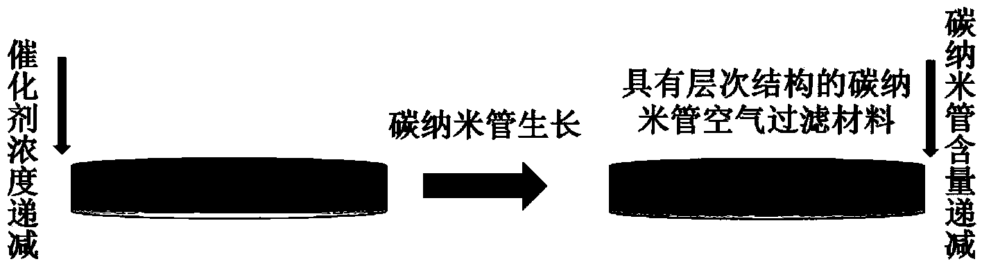
[0047] Embodiment 1, with the quartz fiber filter medium as the base, through the aerosol technology loading catalyst, prepare the carbon nanotube air filter material with gradient structure

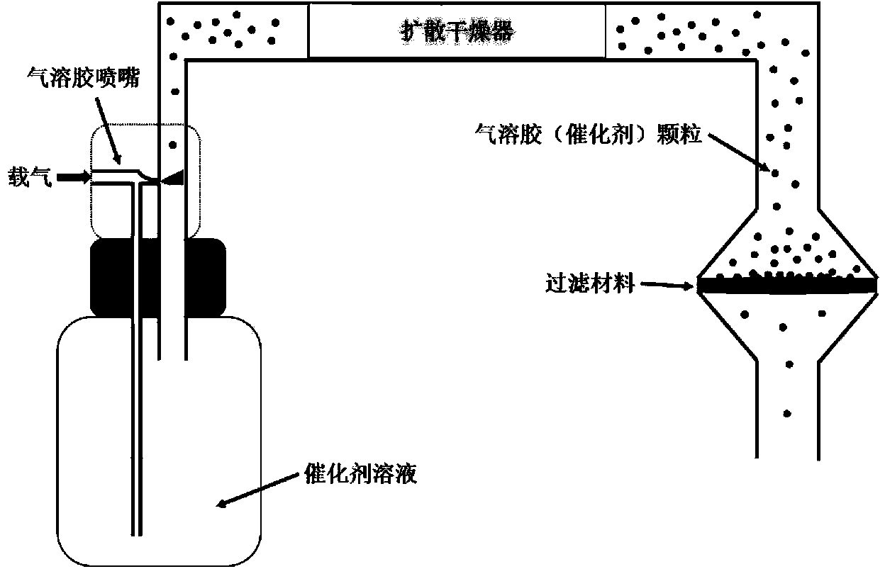
[0048] First, the quartz fiber filter medium (the average fiber diameter is 3 microns, the thickness is 0.43 mm, and the cross section is 100 m 2 ) for catalyst loading, the process is as figure 2 shown.

[0049] The catalyst solution is Fe(NO 3 ) 3 : Al(NO 3 ) 3 0.1 g / ml aqueous solution with a molar ratio of 0.8:1. Fe(NO 3 ) 3 with Al(NO 3 ) 3 After the aerosol particles are diffused and dried, they pass through the quartz fiber filter material. The concentration of aerosol particles can be controlled by adjusting the carrier gas flow of the aerosol nebulizer. In this embodiment, the size of the aerosol particles is 100 nm and the concentration is 3×10 5 per cubic centimeter, the carrier gas is high-purity nitrogen, and the gas velocity is 30mm / s. According to the principl...

Embodiment 2

[0052] Example 2, with the quartz fiber filter medium as the base, the catalyst is loaded by solution impregnation technology, and the carbon nanotube air filter material with gradient structure is prepared

[0053] First, the quartz fiber filter medium (the average fiber diameter is 3 microns, the thickness is 0.43 mm, and the cross section is 100 m 2 ) for catalyst loading. The catalyst solution is Fe(NO 3 ) 3 : Al(NO 3 ) 3 0.1 g / ml aqueous solution with a molar ratio of 0.8:1. Soak the quartz fiber filter medium in the catalyst solution for 6 hours. The filter medium was taken out and placed on a heating plate at 60° C. for 12 hours, during which the thickness direction was kept perpendicular to the heating plate. During the slow heating and drying process, the catalyst will achieve a ladder-like distribution in the thickness direction of the filter material. Carbon nanotube growth was then performed on the catalyst-loaded quartz fiber filter media. In this example,...

Embodiment 3

[0055] Example 3. In-situ preparation of carbon nanotube air filter material with ladder-like structure by planktonic catalytic method

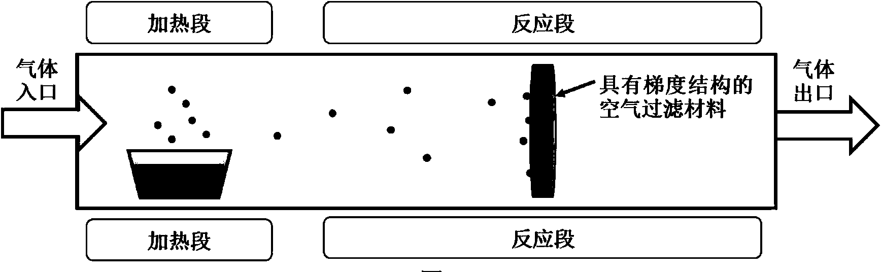
[0056] The schematic diagram of the process of this embodiment is as follows image 3 shown.

[0057] Quartz fiber filter media (the average fiber diameter is 3 microns, the thickness is 0.43 mm, and the cross-section is 100 m 2 ) is placed in the reaction section of the quartz furnace, and the catalyst is ferrocene, which is placed in the heating section. At the beginning of the reaction, a mixed gas is introduced, the ratio is argon: hydrogen: ethylene = 3: 1: 1, and the gas flow rate is 30mm / s. Keep the temperature in the heating section at 120°C and the temperature in the reaction section at 800°C. During this process, the ferrocene is heated and sublimated, and when it passes through the reaction section area, it is heated to form catalyst nanoparticles, which are deposited in the quartz fiber filter medium, and its concentration decre...


PUM

PropertyMeasurementUnit
melting pointaaaaaaaaaa
diameteraaaaaaaaaa
thicknessaaaaaaaaaa

Abstract

The invention discloses a carbon nanotube air filtering material with a gradient structure and a preparation method thereof. The method comprises the following steps: with a fiber filtering medium as a substrate, preparing a metal catalyst; distributing the metal catalyst along the thickness direction of the substrate in a gradient manner; and growing a carbon nanotube on the surface of the fiber filtering medium through a chemical vapor deposition method to obtain the carbon nanotube air filtering material with a gradient structure. The carbon nanotube air filtering material with a gradient structure, provided by the invention, has a multilevel structure, and the carbon nanotube grows on the fiber surface to both solve the strength problem of the nano material in macro scale and fully utilize the excellent performance of the nano material in nano scale; meanwhile, the gradient structure exists in the thickness direction of the filtering material, the design can greatly improve the dust holding capacity of the filtering material, and the prepared filtering material has long service life.

Description

technical field [0001] The invention relates to a carbon nanotube air filter material with a gradient structure and a preparation method thereof, belonging to the technical field of air filter technology and material preparation thereof. Background technique [0002] Air filter materials are widely used in semiconductor industry, pharmaceutical and food industry, automobile industry, nuclear industry, construction industry and other fields to remove particulate matter in the air and protect human health, workplace and product quality. With the development of science and technology and people's increasing awareness of environmental protection and health protection, the market demand for filter materials is also increasing. [0003] The performance indicators for evaluating the quality of air filter materials are mainly effective efficiency, resistance, dust holding capacity and flux. The type of fiber and the arrangement and combination of fibers play a decisive role in the p...

Claims


Application Information

Patent Timeline
Patent Type & Authority Applications(China)
IPC IPC(8): B01D39/14C23C16/26
Inventor 魏飞李朋张莹莹王春雅
Owner TSINGHUA UNIV
Why Eureka
Try Eureka