Step-down converter

A converter and step-down technology, applied to output power conversion devices, instruments, DC power input conversion to DC power output, etc., can solve the problem of increasing chip cost and off-chip area, power consumption, area, and structure Complicated problems, to achieve the effect of saving power consumption, suppressing overshoot current, and simple structure

Inactive Publication Date: 2013-12-25
SHENZHEN INST OF ADVANCED TECH CHINESE ACAD OF SCI
View PDF3 Cites 29 Cited by
  • Summary
  • Abstract
  • Description
  • Claims
  • Application Information

AI Technical Summary

Problems solved by technology

[0005] The traditional soft-start circuit includes two ideas, one is to generate a slowly rising reference voltage through a gradually decreasing frequency clock, so as to generate a slowly rising output voltage through the control circuit, but the disadvantage of this method is that it requires additional The clock control of the complex structure requires additional power consumption and area
Another commonly used m

Method used


Image

  • Step-down converter
  • Step-down converter
  • Step-down converter

Examples


Embodiment Construction

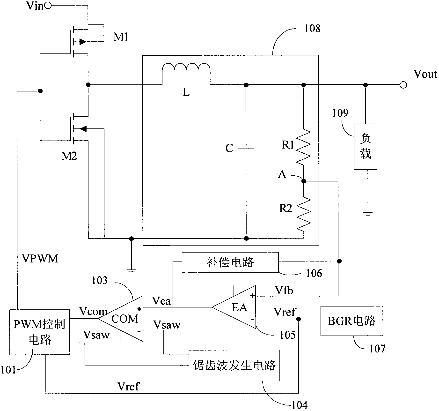
[0026] The invention provides a step-down converter for portable medical equipment or handheld electronic products. The step-down converter is a low-power consumption and high-efficiency step-down (buck) DC-DC converter with a soft start circuit.

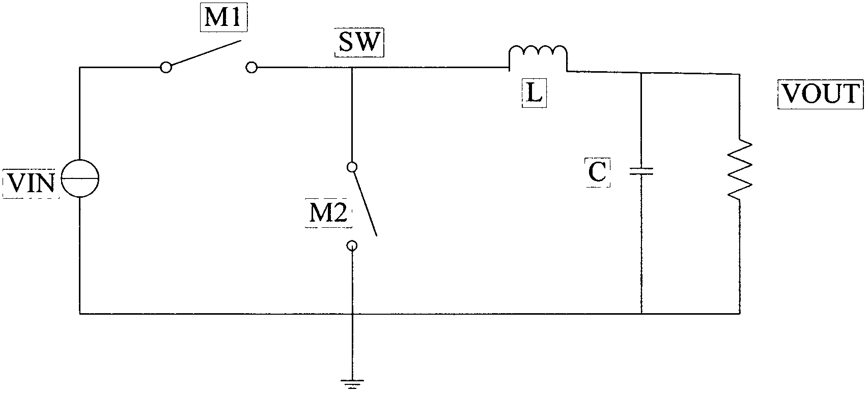
[0027] Such as figure 1Shown is the circuit structure diagram of the step-down converter of the preferred embodiment of the present invention. The buck converter described in this embodiment includes a switching power tube M1, a rectifier tube M2, a pulse width modulation (PWM, pulse width modulation) control circuit 101, a first voltage comparator (COM, comparator) 103, and a sawtooth wave generator. Circuit (sawtooth wave generator) 104, error amplifier (EA, error amplifier) ​​105, compensation (compensation) circuit 106, bandgap reference (BGR, band-gap reference) circuit 107, composed of inductor L, capacitor C, voltage divider resistor R1 and R2 form the power supply module 108. The power supply module 108 described in this e...


PUM


Abstract

The invention provides a step-down converter. The converter comprises a power supply module, a switch power tube, a rectifying tube, an error amplifier, a bandgap reference circuit, a first voltage comparator, a sawtooth wave generating circuit and a pulse width modulation control circuit. The rectifying tube is connected in series with the switch power tube and is further connected to the power supply module. An input voltage is input through the switch power tube and the rectifying tube. The power supply module is used to provide power for a load. The pulse width modulation control circuit is connected to an output terminal of the first voltage comparator, the sawtooth wave generating circuit and the bandgap reference circuit so as to receive a first control signal generated by the first voltage comparator, a sawtooth wave signal and a reference voltage, generate a corresponding second control signal and output the second control signal to the switch power tube and the rectifying tube. The pulse width modulation control circuit comprises a soft start circuit so as to generate a soft start control signal so that the step-down converter is in a soft start mode.

Description

technical field [0001] The present invention relates to a power supply technology, and in particular to a step-down converter for portable electronic equipment. Background technique [0002] The step-down DC-DC (DC-DC) voltage conversion chip adopts a buck structure, which reduces the higher DC voltage to a lower DC voltage, and is widely used in integrated circuits, especially with With the reduction of integrated circuit technology, excessive voltage will break down the metal oxide semiconductor field effect transistor (MOS tube), which may cause the circuit to fail to work, or damage the entire circuit. Therefore, an appropriate power supply voltage can not only protect the circuit, but also effectively reduce the power consumption of the entire system. [0003] Systems used in biomedical engineering are generally powered by batteries or lithium batteries, and are required to be portable and work for a long time. This requires that DC-DC voltage converters used in biome...

Claims


Application Information

Patent Timeline
IPC IPC(8): H02M3/157H02M1/36
Inventor 姚爱萍张金勇王磊
Owner SHENZHEN INST OF ADVANCED TECH CHINESE ACAD OF SCI
Why Eureka
Try Eureka