
Corrosion reaction tester, corrosion evaluation device, and corrosion evaluation method

A technology of corrosion reaction and corrosion evaluation, applied in measurement devices, weather resistance/light resistance/corrosion resistance, instruments, etc., can solve the problems of increased research cost and work intensity, incomparable corrosion rate, and complicated construction of simulation equipment. High accuracy of test results, inhibition of corrosion, and small footprint of the device

Active Publication Date: 2016-01-13
CHINA PETROLEUM & CHEM CORP +1
View PDF7 Cites 0 Cited by
  • Summary
  • Abstract
  • Description
  • Claims
  • Application Information

AI Technical Summary

Problems solved by technology

[0007] US6294387 has provided a kind of iron powder method to measure the method for naphthenic acid corrosion, and this method can get rid of the interference of sulfide to corrosion, has provided good way for simply studying the corrosion of naphthenic acid, but the iron powder method is to corrosive The characterization can only be expressed by the iron content in the oil, which is not comparable to the conventionally used corrosion rate, and the iron powder method uses the method of filtering iron powder to measure the iron content in the oil. When dealing with heavy oil, it is difficult to separate due to the high viscosity
[0008] Zheng Mingguang et al. used a dynamic simulation device for high-temperature corrosion evaluation in "Dynamic Corrosion Evaluation of Crude Oil" (Petrochemical Corrosion and Protection, 2007, 24 (16)), and used nozzles to achieve erosion corrosion under high-temperature and high-velocity conditions of vapor and liquid, but The simulation equipment is complicated to build, occupies a large area, and consumes a lot of oil products, which greatly increases the research cost and work intensity, and is not suitable for laboratory corrosion research

Method used


Image

  • Corrosion reaction tester, corrosion evaluation device, and corrosion evaluation method
  • Corrosion reaction tester, corrosion evaluation device, and corrosion evaluation method

Examples


Embodiment approach

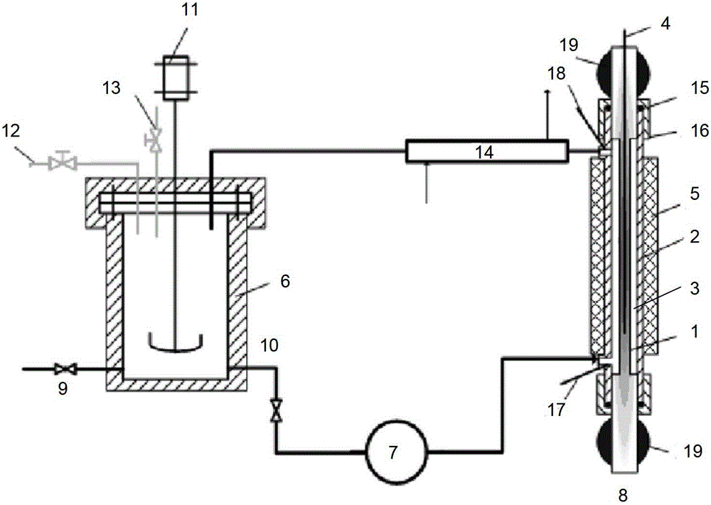
[0050] According to a preferred embodiment of the present invention, the outlet of the cavity 3 of the corrosion reaction tester 8 communicates with the oil sample container 6, so that the oil sample can circulate in the entire corrosion evaluation device. That is, the oil sample to be tested is poured into the oil sample container 6, and the oil sample is transported from the oil sample container 6 to the corrosion reaction tester 8 through the high-precision gear pump 7, from the outlet of the cavity 3 of the corrosion reaction tester 8 (upper end opening), and after passing through the condenser 14, the oil sample flows back to the oil sample container 6 for recycling.

[0051] In order to reduce the impact of high-temperature oil samples on oil sample containers, pumps and pipelines, preferably, such as figure 1 As shown, the outlet of the cavity 3 of the corrosion reaction tester 8 communicates with the oil sample container 6 through a condenser 14 .

[0052] In addition...

Embodiment 1

[0058] (1) Pour 200mL of petroleum acid simulated oil A (prepared from diesel fraction petroleum acid and hydrogenated white oil, with an acid value TAN of 10.1mgKOH / kg) to be tested into the oil sample container 6.

[0059] (2) Introduce nitrogen to purge for 5 minutes, and the test process is under normal pressure, but use a small flow of nitrogen to purge for protection.

[0060] (3) Let the oil sample to be tested enter the corrosion reaction tester 8 through the pump 7 for corrosion testing, then flow out from the outlet of the corrosion reaction tester 8 and condense in the condenser 14, and then flow back to the oil sample container 6 for recycling. Among them, the pump speed of the pump 7 is 10mL / min, the temperature control program of the corrosion reaction tester 8 is set, the temperature of the electric heating rod 1 is 280°C, the heating time is 6min, and the constant temperature time is 3 hours, and the corrosion reaction test is recorded The temperature at the in...

Embodiment 2

[0063] (1) Pour petroleum acid simulated oil A (prepared from diesel fraction petroleum acid and hydrogenated white oil, with an acid value TAN of 10.1 mgKOH / kg) to be tested into the oil sample container 6 .

[0064] (2) Introduce nitrogen to purge for 5 minutes, and the test process is under normal pressure, but use a small flow of nitrogen to purge for protection.

[0065] (3) Let the oil sample to be tested enter the corrosion reaction tester 8 through the pump 7 for corrosion testing, then flow out from the outlet of the corrosion reaction tester 8 and condense in the condenser 14, and then flow back to the oil sample container 6 for recycling. Among them, the pump speed of the pump 7 is 10mL / min, the temperature control program of the corrosion reaction tester 8 is set, the temperature of the electric heating rod 1 is 320°C, the heating time is 6min, and the constant temperature time is 3 hours, and the corrosion reaction test is recorded The temperature at the inlet and...


PUM

PropertyMeasurementUnit
lengthaaaaaaaaaa
volumeaaaaaaaaaa

Abstract

The invention discloses a corrosion reaction tester. The corrosion reaction tester comprises an electric heating rod (1) and a tester coat (2) sleevedly arranged outside the electric heating rod; a cavity (3) having an inlet at one end and an outlet at the other end is formed between the outer wall of the electric heating rod (1) and the inner wall of the tester coat (2), and the interior of the electric heating rod (1) is insertedly provided with a temperature control thermocouple (4). The invention also provides a corrosion evaluation device comprising the corrosion reaction tester and a corrosion evaluation method implemented by utilizing the corrosion evaluation device. The corrosion evaluation device provided by the invention is a corrosion evaluation device which not only has less used oil sample, simple operation and small occupied area of the device, but also has small acid loss amount and high corrosion speed, and is rapid, convenient and accurate during a testing process; and the corrosion evaluation method implemented by utilizing the device has high precision and good parallelism.

Description

technical field [0001] The invention relates to a corrosion reaction tester, a corrosion evaluation device including the corrosion reaction tester, and a corrosion evaluation method using the corrosion evaluation device. Background technique [0002] After long-term development and utilization of petroleum resources, thin oil fields have entered the late stage of exploitation, and the degree of poor quality of crude oil has continued to increase, and the proportion of crude oil with acid value in the output has increased year by year. [0003] Petroleum acid can react with iron during petroleum processing, causing equipment corrosion. The corrosion is different from sulfur corrosion. The acid corrosion forms are pitting corrosion, pit corrosion and groove corrosion, which can easily cause device leakage and fire. , temperature, flow rate, medium and other factors make corrosion detection more difficult. Generally, when the acid value of crude oil reaches 0.5mgKOH / g, it will...

Claims


Application Information

Patent Timeline
Patent Type & Authority Patents(China)
IPC IPC(8): G01N17/00
Inventor 李子锋马力张书红
Owner CHINA PETROLEUM & CHEM CORP
Learn More