

In-situ chemical remediation method of soil
A chemical remediation and soil technology, which is applied in the field of remediation of contaminated soil, can solve the problems of incomplete decontamination, failure to reach the depth of drilling, and short maintenance time, so as to achieve convenient and flexible sampling analysis and ensure the quality of soil remediation Effect
- Summary
- Abstract
- Description
- Claims
- Application Information
AI Technical Summary
Problems solved by technology
Method used
Image

Examples
Embodiment 1
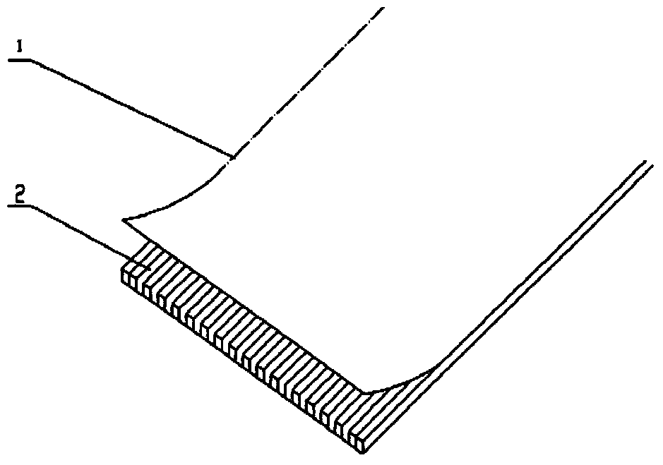
[0035] see figure 1 , an injection device suitable for in-situ chemical remediation of soil, comprising an inner core 1 and a permeable layer 2 covering the periphery of the inner core, wherein the inner core is made of high-density polyethylene (HDPE) and extruded Processed by forming technology, the shape of the inner core is a long flat plate with a width of 10 cm and a thickness of 0.8 cm; the outer surface of the inner core is provided with axial grooves and / or ribs, and the grooves and / or protrusions The ribs are arranged longitudinally to form a channel, and the raised ribs arranged up and down intersect to form a support can prevent the material of the permeable layer from being embedded in the channel due to the pressure of the external soil;
[0036] The material of the permeable layer is non-woven fabric, and its bristle surface faces outwards to the inner core, and the permeation direction is from the inside to the outside, so that the medicine solution can permeat...
Embodiment 2
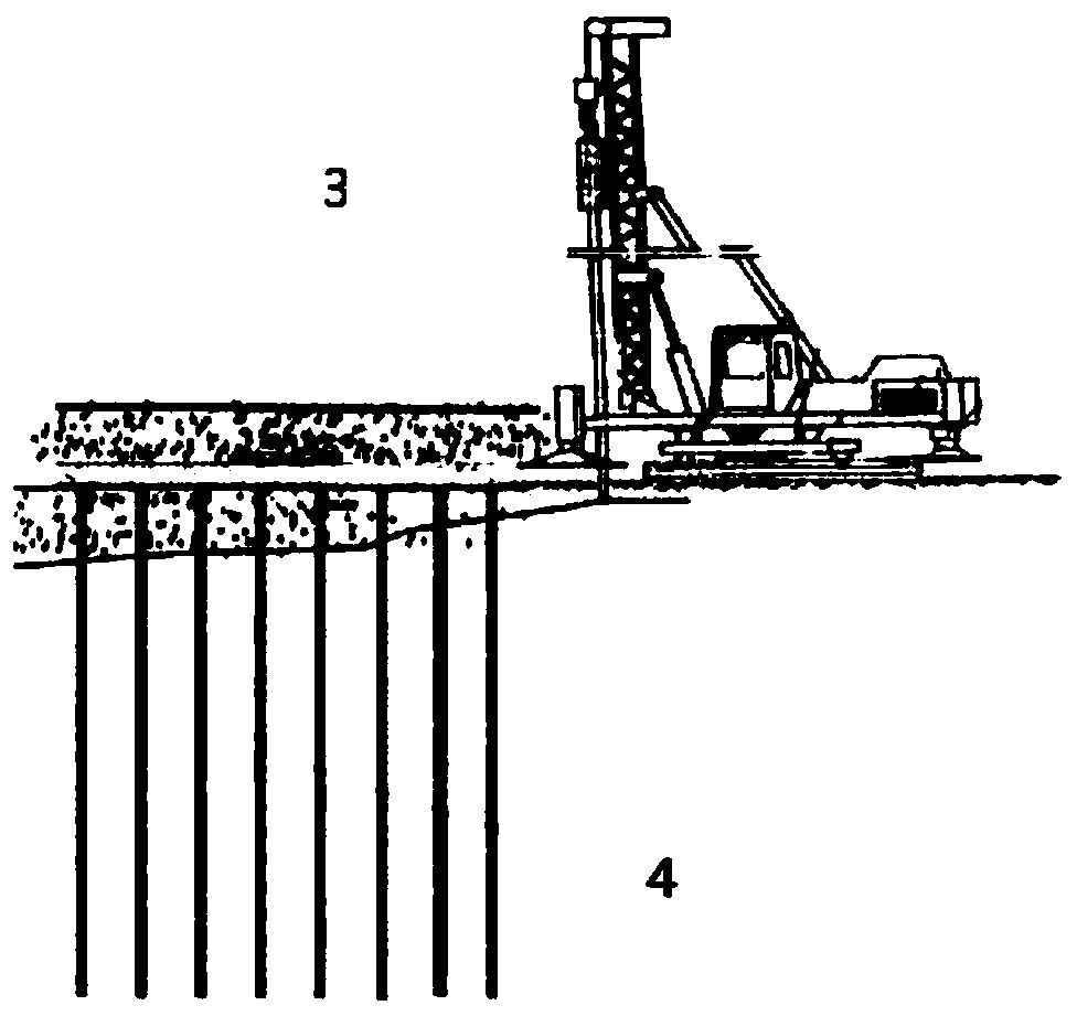
[0038] see figure 2 , a system for arranging the above-mentioned injection device, the system for arranging the above-mentioned injection device is a slot machine 3, including a chassis, a main frame, a vibrating hammer, an intubation tube, and a plug, and the plug is arranged at the front end of the intubation tube. The plug is a round plug; the height of the main frame is 15-30 meters, and the depth is 15-24 meters, and the top is equipped with a pulley head for the lifting and landing of the vibratory hammer; the chassis is a crawler chassis.
[0039] The method for in-situ chemical repairing of soil by using the above-mentioned system with injection device, comprises the following steps:
[0040] (1) After the plug-in machine is in place, use the vibrating hammer to align with the socket and sink, and pass the injection device through the cannula to connect with the plug at the front end. After the cannula is removed, leave the injection device in the soil to complete th...
Embodiment 3
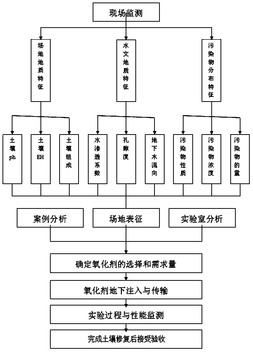
[0045] A method of in-situ chemical oxidation repairing soil, such as image 3 shown, including the following steps:
[0046] (1) Site characterization: In order to better design and implement in-situ oxidation technology, it is necessary to fully understand and characterize the geological and hydrogeological characteristics of the remediation site and the temporal and spatial distribution characteristics of pollutants. It mainly includes the nature, concentration and spatial distribution of pollutants, the determination of chemical parameters such as the amount of pollutants (adsorbed, dissolved, by-products), and the soil properties (alkalinity, pH, Eh), composition, water permeability coefficient, Determination of geological parameters such as porosity and groundwater flow direction. Site characterization adopts the method of combining on-site monitoring with sample collection and laboratory instrument analysis, which is a commonly used standard method in this field.
[0...
PUM
| Property | Measurement | Unit |
|---|---|---|
| Aperture | aaaaa | aaaaa |
Abstract
Description
Claims
Application Information