Reactor for realizing suspension of biofilm carriers under low aeration quantity

A technology of biofilm carrier and aeration rate, applied in the direction of sustainable biological treatment, aerobic process treatment, etc., can solve the problems of complex water quality of production wastewater, secondary pollution, low B/C value, etc., and achieve stable and short-term nitrification Advantages, improved impact load resistance, and the effect of maintaining fluidization characteristics

Active Publication Date: 2014-01-15
BC P INC CHINA NAT PETROLEUM CORP +1
View PDF7 Cites 6 Cited by
  • Summary
  • Abstract
  • Description
  • Claims
  • Application Information

AI Technical Summary

Problems solved by technology

[0002] Refining catalyst production wastewater has complex water quality, high concentrations of suspended solids and ammonia nitrogen, and contains a large amount of inorganic salts and chloride ions, etc., and the B / C value is low, making it difficult to achieve biological treatment
The traditional biological treatment method is currently the most widely used denitrification technology, but the traditional biological treatment technology has the following problems: the process is long and occupies a large area, and the investment cost of infrastructure is high; the system has weak impact resistance and high concentration Ammonia nitrogen wastewater can inhibit the growth of nitrifying bacteria; the acidity generated during the nitrification process needs to be neutralized by adding alkali, which not only increases the treatment cost, but also may cause secondary pollution; the growth of nitrifying bacteria is slow, once the sludge is lost in the suspended sludge system , it is difficult to restore production in a short time; biofilm carrier (biological filler) is difficult to achieve fluidization under low aeration, easy to accumulate, and poor reaction effect

Method used


Image

  • Reactor for realizing suspension of biofilm carriers under low aeration quantity
  • Reactor for realizing suspension of biofilm carriers under low aeration quantity
  • Reactor for realizing suspension of biofilm carriers under low aeration quantity

Examples


Embodiment Construction

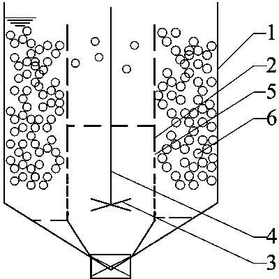
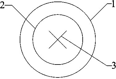
[0022] see figure 1 , figure 2 and image 3 , the present invention provides a reactor for realizing biofilm carrier suspension under low aeration rate, mainly used for treating oil refinery catalyst wastewater, comprising a vertical cylindrical shell 1 coaxially arranged with a vertical Hollow cylinder 2, stirring paddle 3 is installed in the described hollow cylinder, the drive shaft 4 of described stirring paddle can be positioned on the axis of described hollow cylinder, the rotating speed of described stirring paddle is preferably 90rpm, the cylinder wall of described hollow cylinder Several through holes 5 are opened on the top, the bottom end of the hollow cylinder is fixedly connected with the bottom end of the housing, and the annular space between the hollow cylinder and the housing is filled with a biofilm carrier 6, so The bottom end of the hollow cylinder and the bottom end of the housing can be sealed, or a gap can be left, the size of the gap does not allow t...


PUM


Abstract

The invention relates to a reactor for realizing suspension of biofilm carriers under low aeration quantity. The reactor comprises a vertical cylindrical shell, wherein a vertical hollow cylinder is coaxially arranged in the shell, and a stirring paddle is mounted in the hollow cylinder; a plurality of through holes are formed on the wall of the hollow cylinder; the bottom end of the hollow cylinder is fixedly connected with the bottom end of the shell; and the biofilm carriers are filled in a circular space between the hollow cylinder and the shell. According to the unique structure design of the reactor and the control to the rotating speed of the stirring paddle, the biofilm carriers in the reactor can be ensured always in the suspension state under the low aeration quantity, and excellent fluidization character is maintained, so that the partial nitrification advantages are stably kept, the advantages are created for simultaneous nitrification and denitrification, and the aeration energy consumption and the carbon source material consumption in the denitrification phase are reduced.

Description

technical field [0001] The invention relates to a biofilm reactor, in particular to a reactor capable of realizing biofilm carrier suspension under low aeration. Background technique [0002] Refining catalyst production wastewater has complex water quality, high concentrations of suspended solids and ammonia nitrogen, and contains a large amount of inorganic salts and chloride ions. The B / C value is low, and it is difficult to achieve biological treatment. The traditional biological treatment method is currently the most widely used denitrification technology, but the traditional biological treatment technology has the following problems: the process is long and occupies a large area, and the investment cost of infrastructure is high; the system has weak impact resistance and high concentration Ammonia nitrogen wastewater can inhibit the growth of nitrifying bacteria; the acidity generated during the nitrification process needs to be neutralized by adding alkali, which not ...

Claims


Application Information

Patent Timeline
Patent Type & Authority Applications(China)
IPC IPC(8): C02F3/02
CPCY02W10/10
Inventor 高大文周华堂赵庆良陈扬陶卫克胡威夷周戈贾东辉胡奇赵小晶
Owner BC P INC CHINA NAT PETROLEUM CORP
Why Eureka
Try Eureka