Automatic MIG (metal-inert gas) welding method for hard alloy and steel

A technology of hard alloys and welding methods, applied in welding equipment, welding/welding/cutting items, arc welding equipment, etc., can solve problems such as reducing the performance of hard alloys, improve bonding force, solve low productivity, and improve automation horizontal effect

Active Publication Date: 2014-01-29
SHANGHAI UNIV OF ENG SCI
View PDF4 Cites 9 Cited by
  • Summary
  • Abstract
  • Description
  • Claims
  • Application Information

AI Technical Summary

Problems solved by technology

[0004] In order to solve these problems, many practical technologies have been proposed, such as A Costa, R M Miranda, L. Quintino proposed an automatic welding technology for laser welding: Materials Behavior in Laser Welding of Hardmetals to Steel, Materials and Manufacturing Processes, 2006, 21(5), 459-465. The use of laser welding for the connection of cemented carbide and steel solves the problem of the connection between cemented carbide and steel depending on heating and heating in the furnace. The problem of size limitation makes it possible for the connection production of cemented carbide and steel to enter the stage of industrial automation. A method to control the quality of the weld seam by controlling the heat input and the laser action position is proposed, which can effectively suppress the interface reaction and improve the quality of the weld seam. However, due to the large difference in thermal expansion coefficient between cemented carbide and steel and the lack of a certain intermediate layer of buffer material in the welding process, the tungsten carbide in the heat-affected zone on the cemented carbide side of the joint often dissolves in a large area, reducing the hardness. The original properties of the alloy

Method used


Image

  • Automatic MIG (metal-inert gas) welding method for hard alloy and steel
  • Automatic MIG (metal-inert gas) welding method for hard alloy and steel
  • Automatic MIG (metal-inert gas) welding method for hard alloy and steel

Examples


Embodiment Construction

[0036] The technical solutions of the present invention are further described below with reference to the accompanying drawings and embodiments.

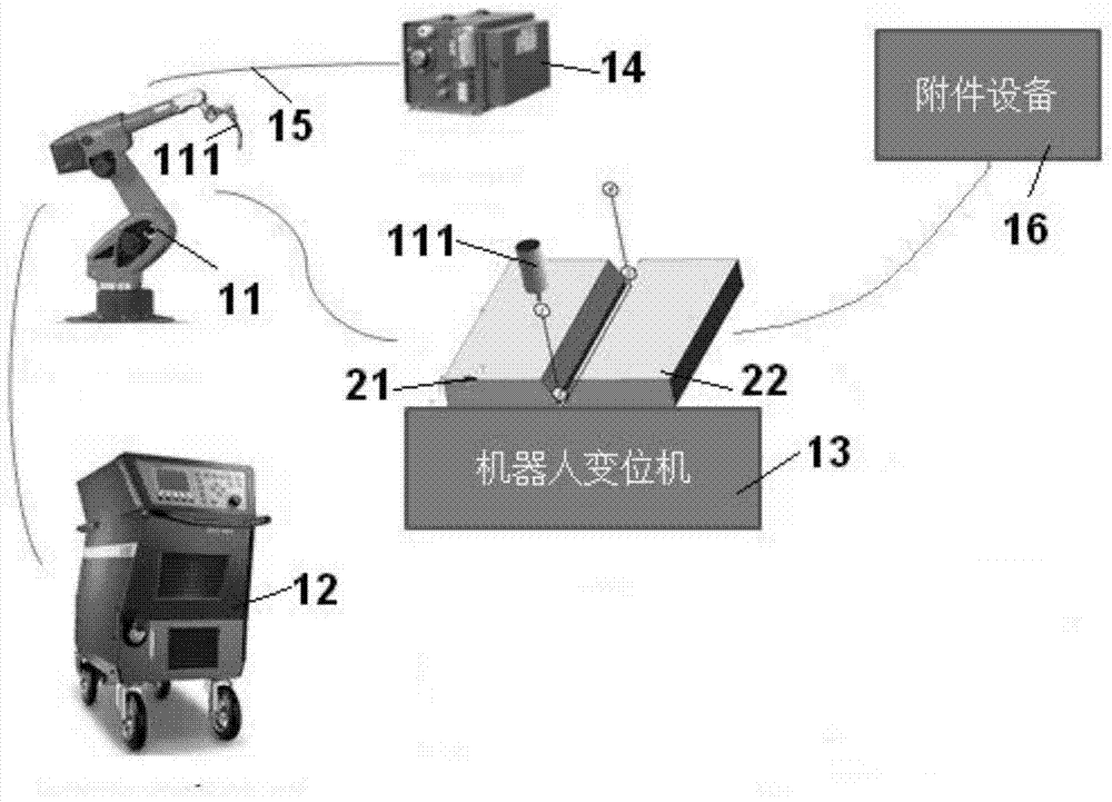
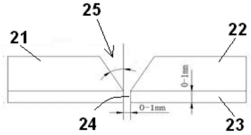
[0037] like figure 1 , figure 2 As shown in the schematic diagram of automatic welding of cemented carbide robot MIG, the welding robot 11 is connected with the welding machine 12 to realize data synchronization, and the material to be welded is cut as required and subjected to pre-welding processing according to the assembly requirements (the material to be welded can be left 0-1mm gap for easy forming) is fixed on the robot positioner 13; the wire feeding mechanism 14 attached to the welding robot 11 completes the feeding of the welding wire 15; the welding machine 12 inputs the program into the robot, inserts the process parameters, The machine controls the operation of the process parameters in real time, and the welding robot 11 performs automatic welding; other accessories such as the accessory equipment 16 refer to the temp...


PUM

PropertyMeasurementUnit
diameteraaaaaaaaaa

Abstract

The invention discloses an automatic MIG (metal-inert gas) welding method for hard alloy and steel. The automatic MIG welding method includes steps of firstly, removing surface oil stain and an oxidation film layer on welded surfaces of welded materials which are hard alloy and steel in thickness ranging from 2mm to 6mm and are uniform in thickness; respectively fixing the hard alloy and the steel on a worktable of a robot position changing machine, keeping a gap between the welded surface of the hard alloy and the welded surface of the steel within 1mm; delivering protective gas which is argon gas or helium gas, adjusting protective gas flow within 15-25L/min; moving a welding gun over the welding surfaces of the welded materials, starting automatic welding and finally performing post-welding inspection. Accordingly, the problems of low productivity, proneness to generating cracks at welding joints and the like in the prior art can be effectively solved, binding force between the hard alloy and the steel is improved, automation level of welding of the hard alloy is improved, durability of the welding joints of the hard alloy is improved, and strength and durability are integrated.

Description

technical field [0001] The invention relates to the technical field of cemented carbide connection, more specifically, relates to a welding method for MIG automatic welding of cemented carbide and steel. Background technique [0002] The carbide content of cemented carbide is usually between 70-97wt%, and the average grain size is between 0.2μm-20μm (market products). Among them, WC-Co-based cemented carbide is more common and is often used in tools and cutting tools, oil and gas transportation Preparation of tooling equipment, etc. It is usually applied in the form of solid carbide, tungsten carbide coating, thick plate connectors, and thin plate connectors; it comprehensively utilizes the strength and toughness of cemented carbide, the hardness of carbide coating, stainless steel / carbon steel / Invar alloy, etc. The steel structure can meet the actual needs of certain parts of the structure for high temperature resistance, heat resistance, and corrosion resistance. In orde...

Claims


Application Information

Patent Timeline
Patent Type & Authority Applications(China)
IPC IPC(8): B23K9/16B23K9/235B23K9/23
CPCB23K9/164B23K9/173B23K9/232B23K9/235B23K2103/18
Inventor 马丁徐培全王臻杰蒋天颖张宏鹏徐振曹晓莲
Owner SHANGHAI UNIV OF ENG SCI
Why Eureka
Try Eureka