Method and device for recovering sulphur in acidic gas, and reactor

A technology for acid gas and sulfur recovery, which is applied in separation methods, chemical instruments and methods, and separation of dispersed particles. It can solve problems such as failure of sulfur recovery devices, failure of normal operation of combustion furnaces, and large concentration fluctuations, so as to reduce catalysts. Consumption and cost, increasing equipment and investment, and improving sulfur conversion and sulfur recovery effects

Inactive Publication Date: 2014-02-12
杭州林达化工技术工程有限公司
View PDF6 Cites 4 Cited by
  • Summary
  • Abstract
  • Description
  • Claims
  • Application Information

AI Technical Summary

Problems solved by technology

Since the industrialization of the Claus recovery process in the 1930s, it has been widely used in the processing of coal, oil, and natural gas such as synthetic ammonia and methanol raw gas production, refinery gas production, and natural gas purification. It has the ability to directly process H 2 S generates sulfur and saves SO compared with acid production 2 Pipeline transportation cost and acid desulfurization cost, high safety and other advantages, but with acid recovery H 2 Compared with S, the one-time investment cost is high
[0008] Acid gas H treated by conventional improved Claus sulfur recovery process 2 The lower limit of S concentration is 15-20%. However, the composition of acid gas in my country's coal chemical industry is complex, and it often comes directly from synthesis gas purification such as low-temperature methanol washing. Therefore, the sulfur content is generally low (≤15%), and the concentration fluctuates greatly (7-15%). 20%), these two characteristics cause the combustion furnace in the main reaction section of the existing coal chemical acid gas Claus sulfur recovery device to fail to operate normally, and it is difficult to obtain quantitative SO 2 Guarantee the H required by the Claus reaction in the conversion section 2 S / SO 2 = 2:1 ratio, resulting in exhaust gas exceeding the standard, and the entire sulfur recovery unit cannot operate

Method used


Image

  • Method and device for recovering sulphur in acidic gas, and reactor
  • Method and device for recovering sulphur in acidic gas, and reactor
  • Method and device for recovering sulphur in acidic gas, and reactor

Examples


Embodiment 1

[0056] Such as Figure 4 The apparatus shown consists of successively connected hydrohydrolysis reactors R 1 , the first heat exchanger E 1 , catalytic oxidation reactor R 2 , the second heat exchanger E 2 , air heater E 3 , condenser E 4 , liquid sulfur separator V 1 , water separator V 2 And tail gas scrubber C 1 , the second heat exchanger E 2 The shell side outlet and the first heat exchanger E 1 Shell side inlet connection, first heat exchanger E 1 The shell side outlet and hydrohydrolysis reactor R 1 Inlet Connection, Air Heater E 3 The shell side outlet and the catalytic oxidation reactor R 2 connect.

[0057] The above-mentioned hydrohydrolysis reactor R 1 and catalytic oxidation reactor R 2 Both horizontal and vertical reactors can be used.

[0058] The acid gas first passes through the second heat exchanger E 2 , the first heat exchanger E 1 and out of the hydrohydrolysis reactor R 1 The gas heat exchange raises the temperature, and then enters the...

Embodiment 2

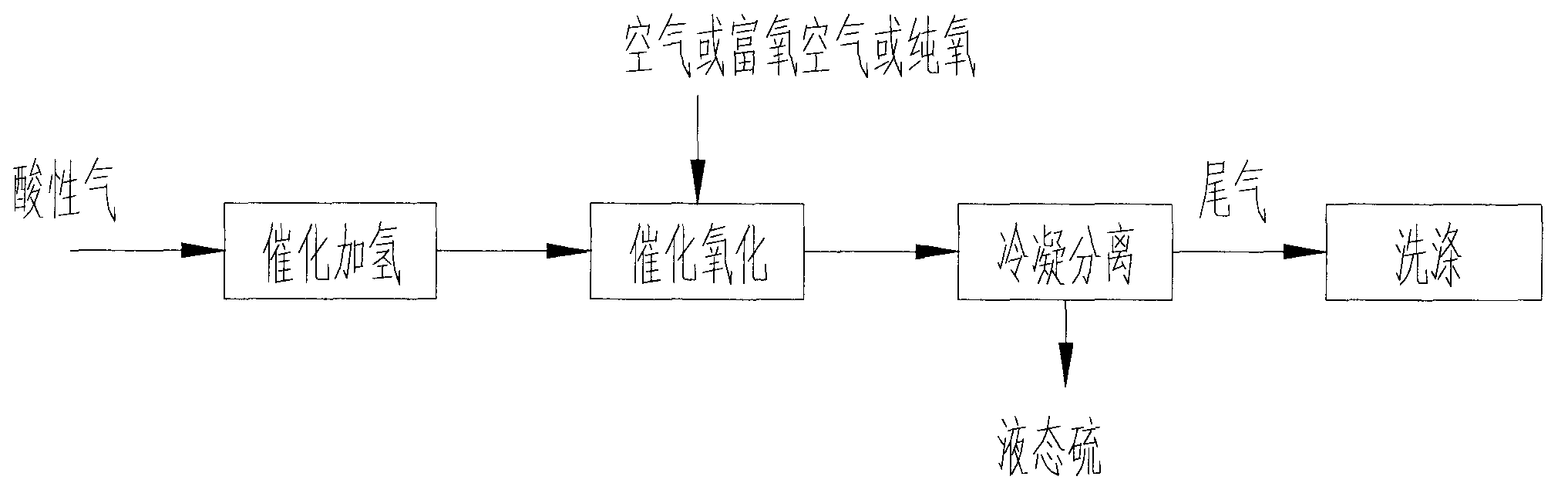
[0060] achieve as figure 1 During the shown process, the two steps of catalytic hydrogenation and catalytic oxidation can be carried out in the same reactor, that is, the design of the present invention is as follows: Figure 5 In the horizontal reactor shown, the interior of the reactor is divided into two chambers by a vertical partition: adiabatic hydrolysis reaction chamber R 1a and water-cooled heat exchange catalytic oxidation reaction chamber R 2a , the acid gas from the hydrolysis reaction chamber R 1a The top enters, and the hydrogenation hydrolysis reaction is carried out in the catalyst layer. The organic sulfur in the acid gas is hydrolyzed into inorganic sulfides, and the reactor starts from the hydrogenation catalytic reaction chamber R 1a The bottom exits the reactor, and then enters the catalytic oxidation reaction chamber R 2a Carry out catalytic oxidation reaction, catalytic oxidation reaction chamber R 2a The inside is a water-cooled heat exchange reacto...

Embodiment 3

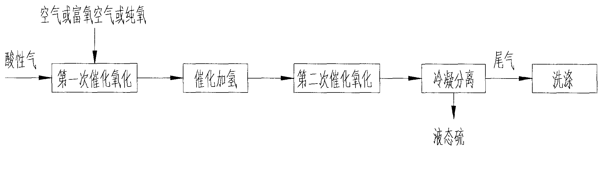
[0062] achieve as figure 2 In the process shown, the first three steps of catalytic oxidation, catalytic hydrogenation and second catalytic oxidation can be carried out in the same reactor, using such as Figure 6 In the horizontal reactor shown, the interior of the reactor is divided into three chambers by two vertical partitions, and the middle chamber is the hydrolysis reaction chamber R 1a , the two sides are respectively the first catalytic oxidation reaction chamber R 2a and the second catalytic oxidation reaction chamber R 2b .

[0063] Acid gas advanced first catalytic oxidation reaction chamber R 1a , part of the hydrogen sulfide reacts with oxygen to generate sulfur and water, and then enters the hydrolysis reaction chamber R 1a Carry out catalytic hydrogenation reaction, hydrolyze organic sulfur into inorganic sulfide, and acid gas enters the second catalytic oxidation reaction chamber R 2b The second catalytic oxidation reaction is carried out to catalyticall...


PUM


Abstract

The invention discloses a method for recovering sulphur in an acidic gas. The method comprises the following steps of: carrying out hydrogenating hydrolysis on organic sulphur in the acidic gas by a catalytic hydrogenation reaction to obtain an inorganic sulphide, catalytically oxidizing the inorganic sulphide to obtain sulphur, then cooling and condensing the reaction gas after the catalytic oxidation to separate liquid-state sulphur, then washing and absorbing the residual sulphide in the tail gas after sulphur separation by alcohol-containing washing solution from low-temperature methanol washing, so as to realize complete recovery for sulphur. The invention further discloses a device used for realizing the method aforementioned and a reactor. The process, device and reactor disclosed by the invention are suitable for sulphur recovery for the acidic gas with a low-concentration H2S content, and the tail gas after desulfurization is washed and treated by virtue of alcohol-containing solution in a low-temperature methanol washing process, thus reducing the content of sulphides in the tail gas and protecting environment; meanwhile, the reactor disclosed by the invention is simple and reasonable in structure, and capable of saving equipment floor space and reducing project investment.

Description

technical field [0001] The invention relates to the technical field of sulfur-containing industrial gas treatment, in particular to a method and device for recovering sulfur from acid gas, which is suitable for sulfur recovery in oil refining, coal chemical industry, petrochemical industry and natural gas processing and production. Background technique [0002] In the existing sour sulfur-containing industrial gas treatment technology, the Claus process (original Claus process) is commonly used, and the reaction is as follows: [0003] [0004] In order to control the reaction temperature, this process can only be carried out at a very low space velocity, which is difficult to use in large-scale industrial devices. Later, an improved Claus process appeared, and the H 2 S oxidation is carried out in two stages, and the reaction is as follows: [0005] [0006] [0007] It can be seen from the above reaction formula that only H is reacted in the first step 2 1 / 3 of ...

Claims


Application Information

Patent Timeline
Patent Type & Authority Applications(China)
IPC IPC(8): B01D53/88B01D53/48B01D53/14
Inventor 楼韧楼寿林
Owner 杭州林达化工技术工程有限公司
Why Eureka
Try Eureka