
High-voltage plasma membrane switch and manufacture method thereof

A plasma and membrane switch technology, which is applied in the field of pyrotechnics, can solve the problems of low trigger energy, high trigger energy, and short response time, and achieve the effects of low trigger energy, reduced trigger energy, and fast response speed

Inactive Publication Date: 2014-02-26
UNIV OF ELECTRONICS SCI & TECH OF CHINA
View PDF2 Cites 17 Cited by
  • Summary
  • Abstract
  • Description
  • Claims
  • Application Information

AI Technical Summary

Problems solved by technology

[0004] The purpose of the present invention is to provide a high-voltage plasma membrane switch and its manufacturing method for the defect of high trigger energy of the high-voltage switch for the existing shock plate detonator. The high-voltage switch has low trigger energy, short response time, high temperature resistance, and high insulation. It has the advantages of small size and easy integration with explosive foil, etc., and the preparation method is simple and the manufacturing cost is low

Method used


Image

  • High-voltage plasma membrane switch and manufacture method thereof
  • High-voltage plasma membrane switch and manufacture method thereof
  • High-voltage plasma membrane switch and manufacture method thereof

Examples


Embodiment Construction

[0023] The present invention will be further explained in detail below in conjunction with specific embodiments and accompanying drawings.

[0024] The preparation process of the high-voltage plasma membrane switch of the present invention is as follows:

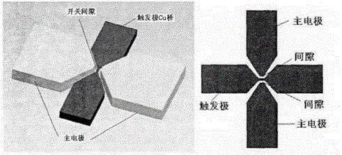
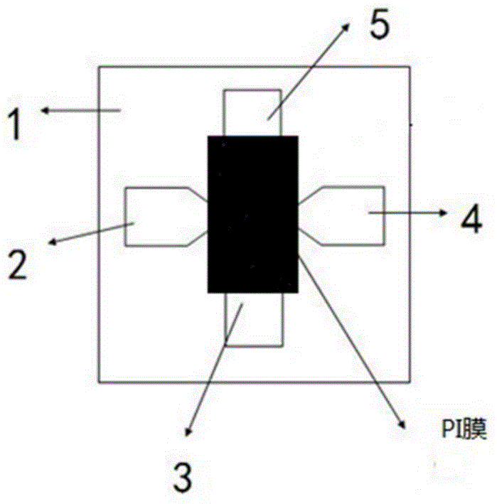
[0025] (1) Select a high-purity alumina substrate with a radius of 3 inches or 2 inches, clean it successively with acetone, alcohol, deionized water, and ultrasonic waves, and then use screen printing technology to deposit 4 on the surface of the substrate according to the designed pattern. Silver electrode, the thickness of the electrode is 2-4um, and its graphic distribution is as follows Figure 4 As shown, the electrodes 2 and 4 are used as trigger electrodes, the distance between the two trigger electrodes is 0.5mm, and the electrodes 3 and 5 are used as the main electrodes, and the distance between the two main electrodes is 1.3mm;

[0026] (2) Overlay the substrate on which the electrodes have been deposited and the...


PUM

PropertyMeasurementUnit
radiusaaaaaaaaaa

Abstract

The invention aims to provide a high-voltage plasma membrane switch and a manufacture method thereof and overcomes the defects that a high-voltage plasma membrane switch for an existing slapper plate detonator is high in trigger energy and poor in work stability. The technical scheme is as follows: the high-voltage plasma membrane switch comprises an insulation base, switch electrodes and a polyimide film, wherein the switch electrodes are distributed on the insulation base and are covered with the polyimide film; the switch electrodes comprise two trigger electrodes and two main electrodes; two trigger electrodes are connected through multiple layers of composite energetic bridge membranes; the main electrodes are positioned on the side surfaces of the bridge membranes and a switch gap is reserved among the main electrodes and the bridge membranes. The high-voltage switch has the advantages of low trigger energy, short response time, high temperature resistance and high insulation property and the like; the high-voltage switch is small in volume and can be easily integrated with an explode foil, so that the high-voltage switch is further applicable to a new-generation slapper plate detonator; further, in the manufacturing process, the magnetron sputtering and a mask process are adopted to deposite the multiple layers of composite energetic bridge membranes between the two trigger electrodes so as to connect the two trigger electrodes; the process flow is simple and is low in manufacture cost.

Description

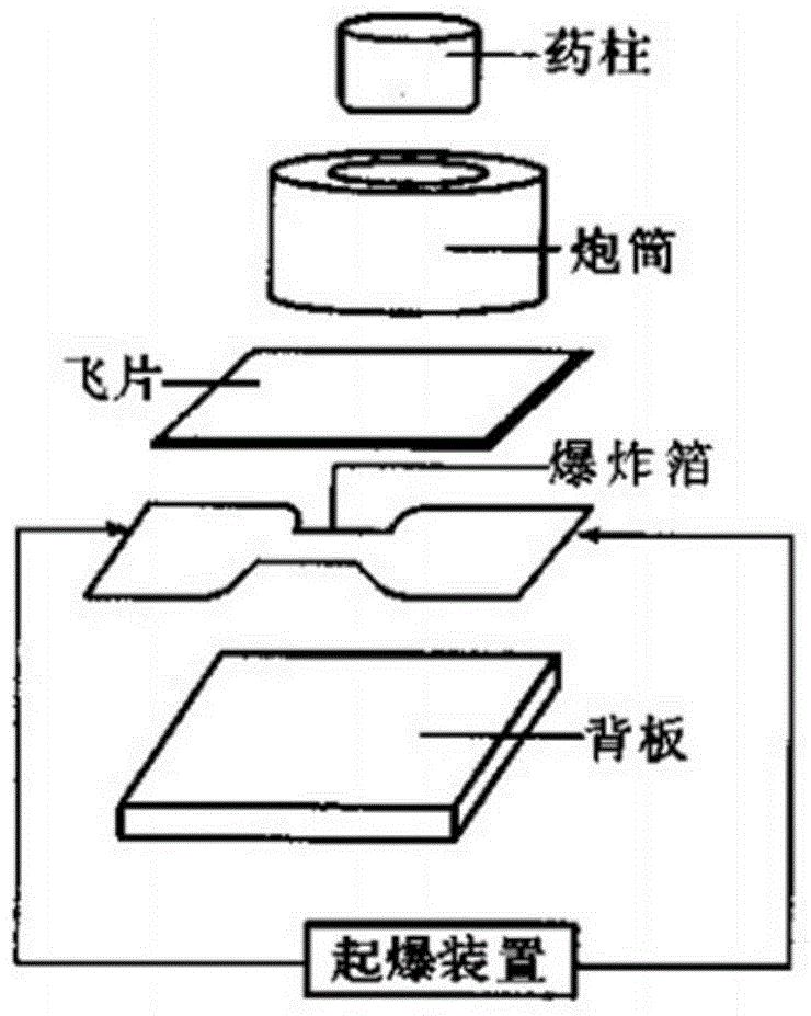
technical field [0001] The invention belongs to the field of pyrotechnics, and relates to a high-voltage switch for a shock plate detonator, in particular to a high-voltage plasma membrane switch and a manufacturing method thereof. Background technique [0002] As an important detonating component in various ignition devices, detonators are widely used in military and civilian fields such as aviation, aerospace, missile launch, and mine blasting. Shock plate detonator as a new type of detonator, such as figure 1 As shown, there is no direct contact between the explosive foil and the explosive, resistance to mechanical shock, radio frequency, static electricity, stray current and electromagnetic interference, and rapid and reliable action. It is currently the most widely used detonator system. Its main working principle is: when the trigger signal comes, the capacitor discharges to generate a large pulse current to change the bridge foil from solid state to plasma state, and...

Claims


Application Information

Patent Timeline
Patent Type & Authority Applications(China)
IPC IPC(8): F42C19/12C23C14/35C23C14/04
Inventor 蒋洪川张宇新蔡贤耀张万里邓新武
Owner UNIV OF ELECTRONICS SCI & TECH OF CHINA
Learn More