Auxiliary electric arc ion plating device for coupling rotary transverse magnetic field with axial magnetic field

An arc ion plating and axial magnetic field technology, applied in ion implantation plating, sputtering plating, vacuum evaporation plating, etc. The effect of target utilization

Active Publication Date: 2014-03-19
INST OF METAL RESEARCH - CHINESE ACAD OF SCI
View PDF7 Cites 5 Cited by
  • Summary
  • Abstract
  • Description
  • Claims
  • Application Information

AI Technical Summary

Problems solved by technology

Using this process, the large particles on the surface of the film are significantly reduced, and the uniformity of film deposition is also improved. However, the electromagnetic field coil installed in the vacuum chamber is prone to charge accumulation in the arc plasma space and high-temperature baking during the film deposition process. Greatly reduced
Therefore, it is necessary to control the movement of the arc spot through the magnetic field to reduce the emission of large particles on the target surface, and it is still difficult to solve the uniformity of the plasma transmission process.

Method used


Image

  • Auxiliary electric arc ion plating device for coupling rotary transverse magnetic field with axial magnetic field
  • Auxiliary electric arc ion plating device for coupling rotary transverse magnetic field with axial magnetic field
  • Auxiliary electric arc ion plating device for coupling rotary transverse magnetic field with axial magnetic field

Examples


Embodiment 1

[0033] An important feature of arc ion plating is that the arc spot discharge forms a high temperature area near it, and it will radiate to other positions in the vacuum chamber at the same time, and is limited by the space of the vacuum chamber, the space around the target is also limited, so the arc source When designing, it will be difficult to make a breakthrough if the thinking is limited to the limited space in the vacuum chamber. Especially for the rotating transverse magnetic field design to control arc spot movement, if the rotating transverse magnetic field generator is placed around the target in the vacuum chamber, it will be limited by size and material, although better results can be achieved if conditions permit , but for the large-area deposition required for industrial production, it will be limited in long-term work. Therefore, in the face of wider applications, innovations and breakthroughs are required.

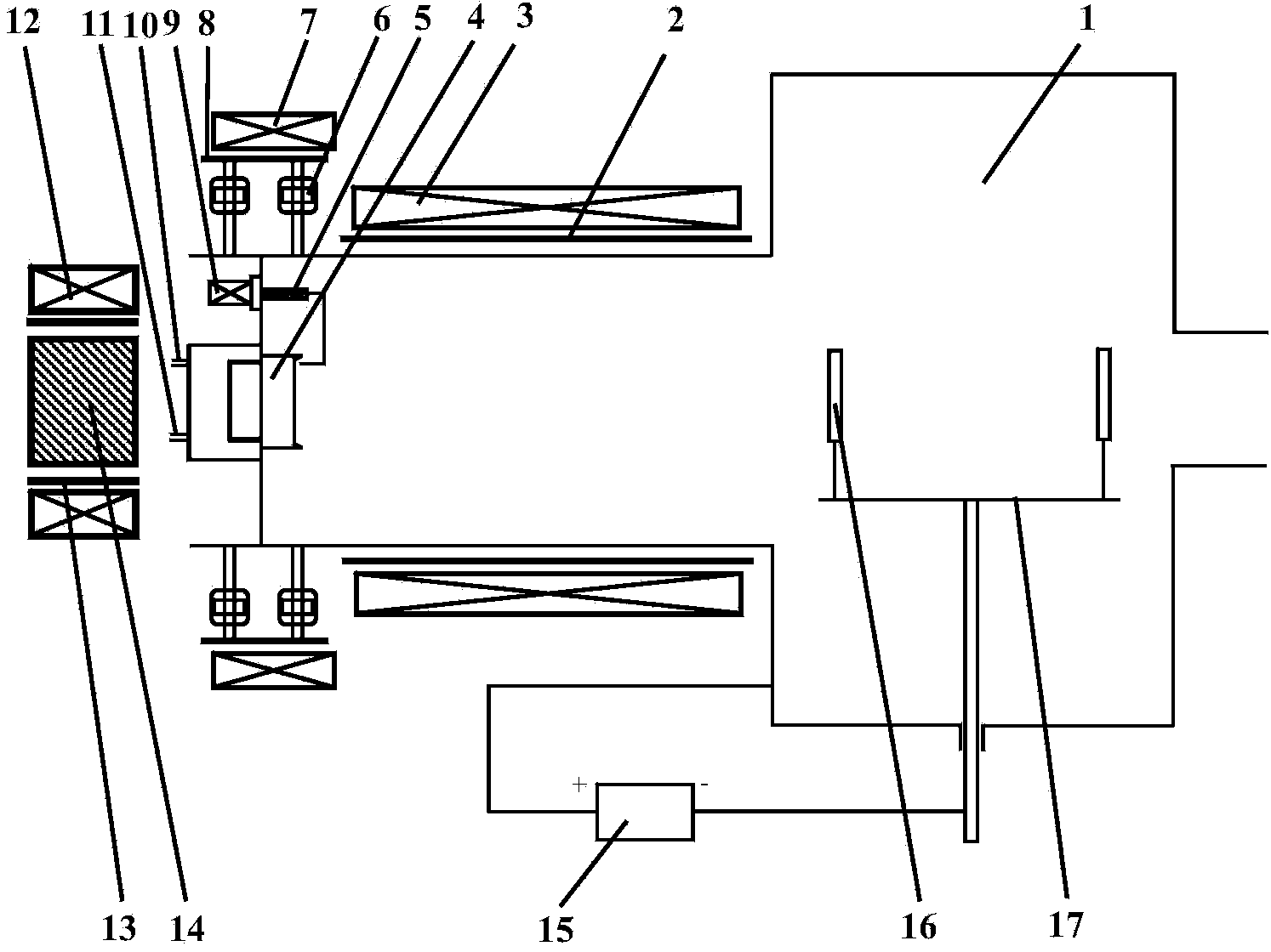
[0034] figure 1 It is a schematic structural diagr...

Embodiment 2

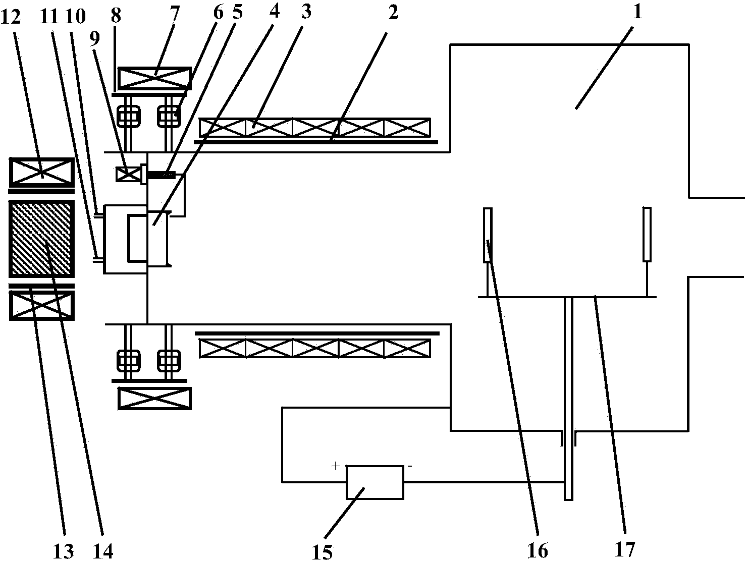
[0040] figure 2 It is an arc ion plating device assisted by a rotating transverse magnetic field coupled with a gradient axial magnetic field invented in Embodiment 2 for small-sized targets, in which the gradient magnetic field is composed of more than two electromagnetic coils, and the magnetic field strength is adjusted separately, and its size is along the direction of the plasma beam. The flow direction gradually decreases. The difference between this embodiment and Embodiment 1 is that the plasma confinement axial magnetic field generator uses a gradient magnetic field, which is composed of more than two electromagnetic coils, and the number of turns of the electromagnetic coil increases with the distance from the target. Decreases in a gradient. Under this condition, each electromagnetic coil can be connected in series to form a large coil. When the coil is energized, the current in each electromagnetic coil is the same, but because the number of turns of different co...

Embodiment 3

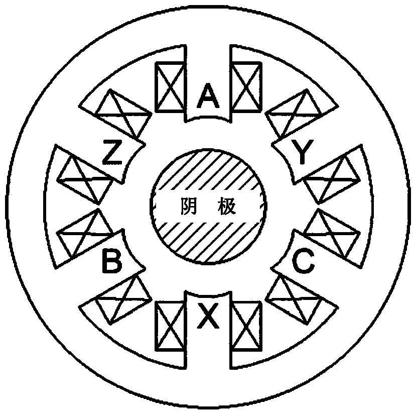
[0042] Different from Embodiment 1, the rotating transverse magnetic field generating device in this embodiment adopts a rotating transverse magnetic field generating device with three phases and six magnetic poles, image 3 It is a schematic diagram of the structure of the three-phase six-pole rotating transverse magnetic field generator used in this embodiment. There are six magnetic poles (A, Y, C, X, B, Z) evenly distributed on the circular closed main magnetic passage. A whole electromagnetic loop skeleton is formed, and the center of the electromagnetic loop skeleton is the cathode. The rotating transverse magnetic field generating device and the target are also coaxially placed, and the position can be adjusted. It is advisable to form an effective rotating magnetic field area on the target surface. The top end of each magnetic pole is straight or arc-shaped, symmetrically pointing to the center of the target surface. In the rotating transverse magnetic field generatin...


PUM

PropertyMeasurementUnit
thicknessaaaaaaaaaa

Abstract

The invention belongs to the field of material surface modification and in particular relates to an auxiliary electric arc ion plating device for coupling a rotary transverse magnetic field with an axial magnetic field, wherein a work table and a target are arranged in a vacuum chamber of the device; the front side of the target is opposite to the work table; an axial magnetic field generation device which is arranged behind the target is sleeved on a flange or a support cylinder and insulating protection is arranged between the axial magnetic field generation device and the flange or the support cylinder; a rotary transverse magnetic field generation device which is arranged outside the vacuum chamber is sleeved on a flange or a support cylinder at the outer side of the target and insulation protection is arranged between the rotary transverse magnetic field generation device and the flange or the support cylinder; an axial magnetic field generation device which is arranged in a plasma transmission channel is sleeved on a flange or a support cylinder on the outer side of the vacuum chamber and insulation protection is arranged between the axial magnetic field generation device and the flange or the support cylinder. The movement of an arc spot is controlled by the rotary transverse magnetic field, so that the discharging manner of the arc spot is improved; the movement speed of the arc spot and the emission of large particles on the surface of the target are improved; meanwhile, the plasma transmission is restrained by the axial magnetic field; and the density and the utilization rate of the plasma are improved.

Description

technical field [0001] The invention belongs to the field of material surface modification, specifically a rotating transverse magnetic field coupling axial magnetic field assisted arc ion plating device, which is used to increase the moving speed of the arc spot, reduce the emission of large particles on the surface of the target material, and improve the deposition rate and deposition uniformity of the film. sex. Background technique [0002] Arc ion is one of the most widely used physical vapor deposition (PVD) technologies in industry. Due to its high ionization rate, high incident particle energy, good diffraction, and a series of advantages such as low temperature deposition, arc ion plating technology has been obtained. Rapid development and wide application. However, due to the existence of large particles in arc ion plating, the performance and service life of coatings and films are seriously affected. Therefore, how to solve the problem of large particles in cath...

Claims


Application Information

Patent Timeline
Patent Type & Authority Applications(China)
IPC IPC(8): C23C14/35
Inventor 赵彦辉肖金泉于宝海
Owner INST OF METAL RESEARCH - CHINESE ACAD OF SCI
Why Eureka
Try Eureka