
Device and method for machining metal beryllium single-blade outer chip removal deep hole

A processing method and technology of a processing device, applied in metal processing equipment, boring/drilling devices, manufacturing tools, etc., can solve the problems of chip breaking and chip removal difficulties, tool erosion, low stress brittle fracture of beryllium workpieces, etc. The effect of processing yield

Inactive Publication Date: 2014-03-26
西北稀有金属材料研究院宁夏有限公司
View PDF7 Cites 11 Cited by
  • Summary
  • Abstract
  • Description
  • Claims
  • Application Information

AI Technical Summary

Problems solved by technology

However, there are two problems that are difficult to solve in the machining of beryllium: 1. Due to the brittleness of beryllium and the sensitivity to notches, when machining beryllium, when the tool leaves or enters the workpiece, edge slag will appear, and even lead to Beryllium workpieces are brittle under low stress; 2. Beryllium has severe tool wear and tear, and it is difficult to ensure machining accuracy. This is because beryllium machining is brittle, and high-hardness chips generate normal stress on the front of the tool and continuously impact the cutting edge. The tool is eroded, and the fine beryllium powder (including beryllium oxide) in the powder metallurgy beryllium also has a grinding effect on the tool, and the cutting edge wears quickly, which is more significant for high-speed steel tools
[0005] In the prior art, for deep hole machining with a ratio of hole depth to hole diameter ≥ 20, special deep hole drilling equipment needs to be used for deep hole machining. This technology mainly has the following problems: 1. Difficulty in chip breaking and chip removal
If the defect rate in the machining process is too high, the cost of the product will be even more astonishing

Method used


Image

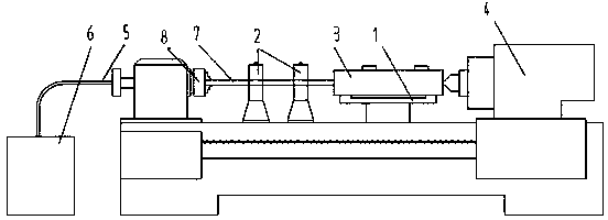
  • Device and method for machining metal beryllium single-blade outer chip removal deep hole

Examples


Embodiment Construction

[0021] The metal beryllium single-edge external chip removal deep hole drilling processing method of the present invention is particularly suitable for small aperture (φ12mm) and large aspect ratio (50-150) deep hole processing of metal beryllium. The specific embodiments of the present invention will be described in detail below with reference to the accompanying drawings.

[0022] 1. According to the size and shape of the beryllium workpiece to be processed, process the auxiliary plate 1 for workpiece clamping. And install the auxiliary board 1 on the middle carriage of the lathe 4 (CA6140), and change the drilling position by moving the middle carriage during processing to realize the processing of the hole system.

[0023] 2. According to the design of the lathe and tool used, design and manufacture the connecting mechanism 5 between the oil supply system and the tool 7, and install it on the lathe for cooling and chip removal during processing. The deep hole drill has a hollo...


PUM


Abstract

The invention relates to a device and method for machining a metal beryllium single-blade outer chip removal deep hole. According to the device, a mounting plate used for clamping a workpiece, a tool bar guiding and supporting sleeve sued for supporting a tool and a connecting structure used for being connected with an oil pressure system and the tool are arranged on a common lathe, the tool is a hard alloy deep hole gun drill and is clamped on a three-jaw chuck of the lathe, the mounting plate is arranged on a middle supporting plate of the lathe, and the tool bar guiding and supporting sleeve is arranged between the three-jaw chuck and the mounting plate. Compared with the prior art, the method for machining the metal beryllium single-blade outer chip removal deep hole solves the problems of chip breakage, chip discharge, cooling, lubrication, guidance, drilling deviation and the like existing in the existing metal beryllium deep hole machining process, and therefore the machining finished product rate of beryllium is effectively improved, the deep hole with a draw ratio of 50-150 and an aperture phi smaller than or equal to 20mm of metal beryllium materials is machined successfully, hole machining precision can reach IT8, and surface smoothness can reach Ra0.8.

Description

[0001] Metal beryllium single-edged outer chip removal deep hole processing device and processing method Technical field [0002] The invention relates to the technical field of non-ferrous metal processing, in particular to a deep hole processing device and a processing method for single-edge external chip removal of beryllium. Background technique [0003] The machining performance of metal beryllium is mainly determined by the mechanical properties of metal beryllium, including hardness, elastic modulus, strength and plasticity, etc. All conventional machining methods can be used to process beryllium, such as turning, milling, grinding, planing, and metal beryllium. , Boring, drilling, reaming, sawing, tapping, etc. Other processing methods such as EDM, EDM drilling, mechanical grinding and polishing, electrochemical corrosion, etc. are also suitable for mechanical processing of beryllium. However, there are two difficult problems in the machining of beryllium: First, due to th...

Claims


Application Information

Patent Timeline
IPC IPC(8): B23B41/02
CPCB23B41/02B23B43/00
Inventor 苏东峰钟景明路炳胜许德美魏建石建军张起龙张月军李志年王滨
Owner 西北稀有金属材料研究院宁夏有限公司
Learn More