Microwave photon receiving method and device

A microwave photonics and receiving method technology, applied in the field of microwave photonics, can solve the problems of disturbance stability, poor signal quality, and increase system cost, and achieve the effects of improving stability, reducing system loss, and reducing cost

Active Publication Date: 2014-03-26
NANJING UNIV OF AERONAUTICS & ASTRONAUTICS
View PDF3 Cites 30 Cited by
  • Summary
  • Abstract
  • Description
  • Claims
  • Application Information

AI Technical Summary

Problems solved by technology

On the one hand, in addition to the semiconductor optical amplifier, this method still needs to add one or more electro-optic modulators to modulate the received radio frequency signal and local local oscillator signal to the light; on the other hand, it is limited by the carrier recovery time of the semiconductor optical amplifier. Limitations, the quality of the signal processed by the final receiver is often poor, and complex post-processing is required to meet the processing requirements of the back-end, which further increases the system cost
In addition, similar to the previous method, a phase locking or phase compensation device is still needed to solve the stability problem caused by the local oscillator phase disturbance

Method used


Image

  • Microwave photon receiving method and device
  • Microwave photon receiving method and device
  • Microwave photon receiving method and device

Examples


Embodiment Construction

[0015] The technical scheme of the present invention is described in detail below in conjunction with accompanying drawing:

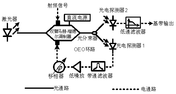
[0016] Microwave photon receiving device of the present invention such as figure 1 As shown, including: light source, dual-drive Mach-Zehnder modulator, DC power supply, optical beam splitter, photodetector 1, photodetector 2, band-pass filter, phase shifter, low-noise amplifier; light source and dual The optical input terminal of the driving Mach-Zehnder modulator is connected to output the optical carrier to the dual-driving Mach-Zehnder modulator; the output terminal of the DC power supply is connected to the DC bias input terminal of the dual-driving Mach-Zehnder modulator to send The Mach-Zehnder modulator provides a DC bias voltage; the output of the dual-drive Mach-Zehnder modulator is connected to the input of the optical beam splitter; one output of the optical beam splitter passes through the photodetector 1 and the band-pass filter in turn ,...


PUM


Abstract

The invention discloses a microwave photon receiving method, and belongs to the technical field of microwave photonics. Firstly, the received radio frequency signal is sent to one radio frequency input port of a dual-drive-Mach-Zehnder modulator; an optical modulation signal outputted by the dual-drive-Mach-Zehnder modulator is divided into two paths, and one of the paths forms a photoelectric oscillation loop which is fed back to the other radio frequency input port of the dual-drive-Mach-Zehnder modulator, wherein oscillation frequency of the photoelectric oscillation loop is close to carrier frequency in the radio frequency signal and sufficient to enable the photoelectric oscillation loop to work under an injection locking mode; DC bias voltage of the dual-drive-Mach-Zehnder modulator is adjusted so that phases between input signals on the two radio frequency input ports are non-orthogonal; and the optical modulation signal outputted by the other path is photo-electrically converted so that a down-conversion base band or an intermediate frequency signal is obtained. The invention also discloses a microwave photon receiving device. The device is high in conversion efficiency, low in loss, simple in structure and low in cost.

Description

technical field [0001] The invention relates to a microwave photon receiving method, in particular to a microwave photon receiving method and device based on an OEO (Optoelectronic Oscilattor, optoelectronic oscillator), and belongs to the technical field of microwave photonics. Background technique [0002] The main function of the microwave receiver in the microwave system is to down-convert the received RF signal, so that the high-frequency RF signal is down-converted to the baseband or intermediate frequency for further signal processing. Usually, microwave receivers are mostly based on electrical mixers, and the nonlinear effect of electrical mixers is used to realize the down-conversion of signals. However, due to the bottleneck of electronic technology, receivers based on electric mixers often have disadvantages such as low conversion efficiency, low isolation between local oscillator and RF port, low operating frequency, narrow operating bandwidth, and large signal d...

Claims


Application Information

Patent Timeline
Patent Type & Authority Applications(China)
IPC IPC(8): H04B10/70H04B10/60
Inventor 潘时龙唐震宙薛敏
Owner NANJING UNIV OF AERONAUTICS & ASTRONAUTICS
Why Eureka
Try Eureka