
Electromagnetic wave shielding structure and flexible printed circuit board with same

A shielding structure and electromagnetic wave technology, applied in printed circuit parts, magnetic/electric field shielding, electrical components, etc., can solve problems such as poor adhesion, and achieve excellent insulation, high thermal stability, and good flame retardancy.

Inactive Publication Date: 2014-03-26
KUSN APLUS TEC CORP
View PDF5 Cites 13 Cited by
  • Summary
  • Abstract
  • Description
  • Claims
  • Application Information

AI Technical Summary

Problems solved by technology

Although the flame retardancy of the electromagnetic wave shielding film can be improved, there is a problem of adhesion between the shielding film and the flexible printed circuit board
In addition, in order to achieve better shielding ability, it is often necessary to fill more conductive powder, but the higher the content of conductive powder, the poorer the adhesion between the shielding film and the flexible printed circuit board.

Method used


Image

  • Electromagnetic wave shielding structure and flexible printed circuit board with same
  • Electromagnetic wave shielding structure and flexible printed circuit board with same
  • Electromagnetic wave shielding structure and flexible printed circuit board with same

Examples


Embodiment 1

[0035]Example 1: Add propylene glycol methyl ether and methyl ethyl ketone to 30 mass parts of thermosetting epoxy resin mixture, 14.5 mass parts of diethylaluminum phosphate powder (Klein Company) and 10 mass parts of aluminum hydroxide powder as a flame retardant Mix solvent (PGME / MEK= 1 / 2) to dilute, disperse and evenly mix the above additives to form an insulating adhesive with a total solid concentration of 30 weight ratio. Lay on black polyimide film (Damaic) and dry to form an insulating adhesive layer.

[0036] In addition, 30 parts by mass of thermosetting epoxy resin mixture, 70 parts by mass of silver-coated copper conductive powder and a mixed solvent containing propylene glycol methyl ether and methyl ethyl ketone (PGME / MEK= 1 / 2) were uniformly mixed and diluted to a total solid concentration The conductive adhesive is 50% by weight, and it is coated on the release surface of the release layer made of polyethylene phthalate (PET), and dried to form a conductive ad...

Embodiment 2~5

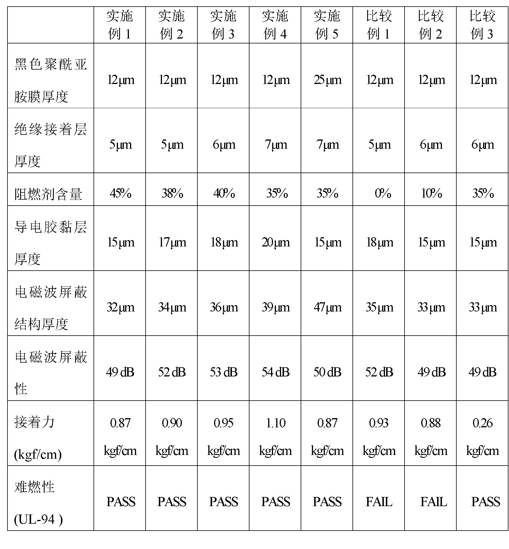
[0038] Examples 2 to 5: The same steps were performed as in Example 1, except that the flame retardant content shown in Table 1 and the thickness of each layer shown in Table 1 were used in the insulating adhesive layer. The prepared electromagnetic wave shielding structure was laminated with the flexible printed circuit board, and the electromagnetic wave shielding property, the adhesion between the flexible and hard printed circuit board and the flame retardancy test results were recorded in Table 1.


PUM

PropertyMeasurementUnit
The average particle sizeaaaaaaaaaa
Thicknessaaaaaaaaaa
Thicknessaaaaaaaaaa

Abstract

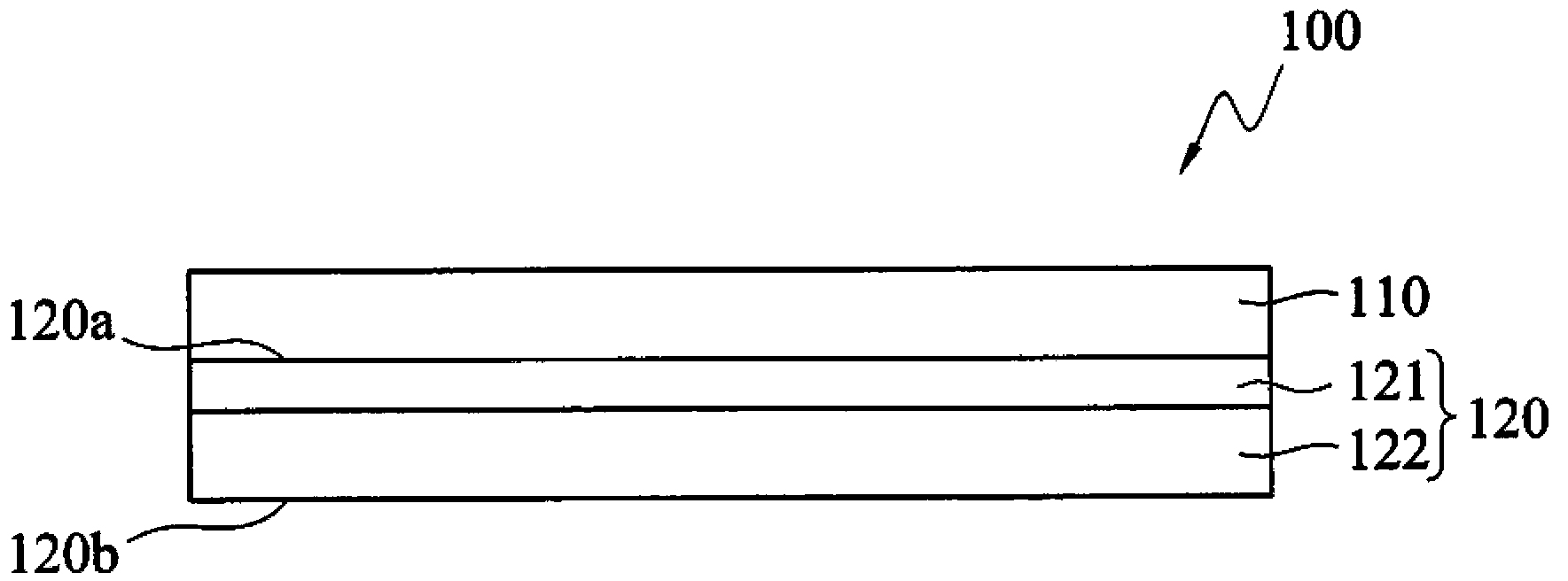
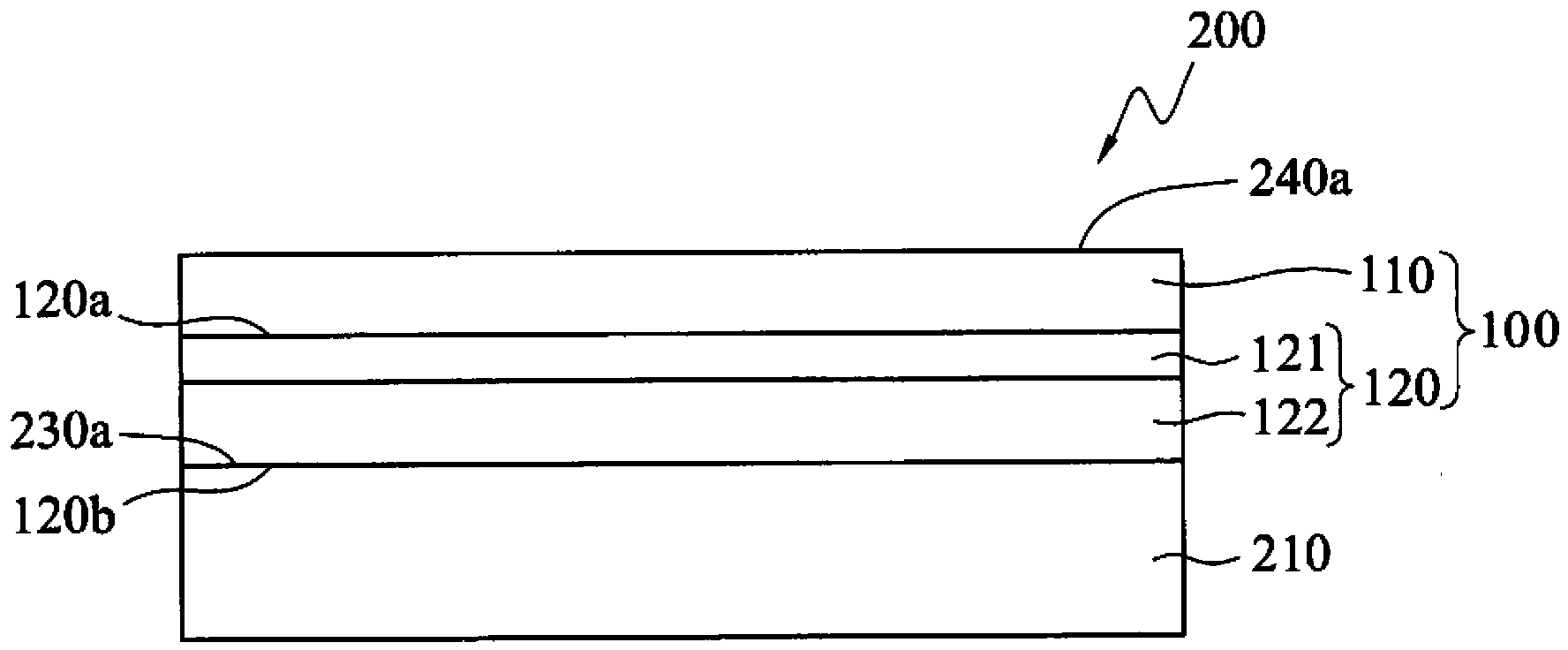
The invention discloses an electromagnetic wave shielding structure and a flexible printed circuit board with same. The electromagnetic wave shielding structure comprises a conducting composite film and a black polyimide film, wherein the conducting composite film comprises an insulating bonding layer and a conducting adhesive layer which are mutually overlapped. Compared with common thermoplastic industrial plastic, the black polyimide film not only has the characteristics of high thermostability, excellent insulating property, mechanical strength and resistance to chemical corrosion and the like, but also has non-bright anti-rotation property, so that circuit patterns are effectively prevented from being plagiarized by the same industry, moreover, as the conducting composite film comprises the insulating bonding layer and the conducting adhesive layer, and the conducting adhesive layer contains fire retardant, fire retardant is not required to be added to the conducting adhesive layer, the effects of optimal UL94 vertical flame test and VTM-0 flame retardant characteristic specification requirements can be achieved, and the flexible printed circuit board with the electromagnetic wave shielding structure can have optimal fire resistance.

Description

technical field [0001] The invention relates to an electromagnetic wave shielding structure, in particular to a shielding film layer used for a flexible printed circuit board with the functions of shielding wiring and electromagnetic interference. Background technique [0002] In order to meet the multi-functional market demand of electronic and communication products, the structure of Flexible Printed Circuit (FPC) needs to be lighter, thinner, shorter, and smaller, and the function requires high-density and multi-function signal transmission. . In addition, as the distance between the signal transmission lines of the flexible substrate is getting closer and closer, and the operating frequency is moving toward high broadband, the electromagnetic interference (Electromagnetic Interference; EMI) from external electromagnetic radiation or internal noise (noise) ) is getting worse. Therefore, it is necessary to formulate various countermeasures against electromagnetic wave in...

Claims


Application Information

Patent Timeline
IPC IPC(8): H05K9/00H05K1/02
Inventor 洪金贤林志铭林惠峰李建辉王俊
Owner KUSN APLUS TEC CORP
Learn More