Eureka AIR delivers breakthrough ideas for toughest innovation challenges, trusted by R&D personnel around the world.

Hollow cast iron tubular product and vertical continuous casting method and special equipment thereof

A technology of vertical continuous casting and special equipment, applied in the field of hollow cast iron pipes, vertical continuous casting methods and special equipment, can solve the problems of dimensional error, deterioration of uniformity of structure and performance, deterioration of fluidity of molten iron, etc. The ratio of the equiaxed crystal region, the effect of improving the mechanical properties, and improving the dimensional accuracy

Inactive Publication Date: 2014-04-09
SHAN XI TONGXIN LIANZHU PIPE IND
View PDF13 Cites 6 Cited by
  • Summary
  • Abstract
  • Description
  • Claims
  • Application Information

AI Technical Summary

Problems solved by technology

This type of scheme has the following defects: one is that the temperature of the molten iron in the crystallizer gradually decreases from bottom to top, and the temperature is the lowest on the top surface of the uppermost part, the fluidity of the molten iron becomes poor, and the inner wall of the formed tube core is rough; the other is Since the continuous casting process is "drawing-pause-drawing-pause-..." alternately, and the pause time is several times or even ten times longer than the drawing time, the molten iron level is relatively static in the tube core during the pause, and the diameter However, the solidification speed is very high, so at this height, the wall thickness of the pipe is obviously thickened, and macroscopically, there is a bamboo-shaped annular boss (or "hoop") on the inner wall of the pipe.
The superposition of the above two defects greatly reduces the dimensional accuracy of the inner hole of the continuous casting hollow cast pipe. According to actual verification, on the continuous casting pipe with an outer diameter of 100-200mm and a wall thickness of 10-20mm, the hoop height is 3-8mm, so that The size error of the inner diameter is as high as 6-16mm; while on the continuous casting pipe with the outer diameter of 200mm or more and the wall thickness of 20mm or more, the hoop height is 5-10mm, so that the size error of the inner diameter is 10-20mm. Such a serious size error makes the continuous casting hollow The market application value of cast pipe has dropped significantly
Third, due to the high cooling rate of the water-cooled crystallizer (under the premise of the same pipe size, its cooling rate is 4-5 times that of centrifugal casting on average, and about 30 times that of sand casting), resulting in The radial temperature gradient is very large, so that the primary dendrites are very developed and can almost penetrate the entire tube wall. Accompanied by this, most of the grain boundaries and graphite sheets in the cast structure are also parallel to the radial direction. This distribution makes the hollow The tangential strength of the cast pipe is greatly reduced; the fourth is that there is no strong convection in the molten iron column in the crystallizer, and the solute distribution gradient is large, resulting in a large difference in the composition of the inner and outer layers of the pipe wall, and the uniformity of the structure and performance becomes poor
The existence of the above four defects shows that although the vertical continuous casting method can be used to draw the cast iron hollow cast pipe, but from the perspective of the shape of the pipe, the size error of the inner hole is too large, which is far from reaching the technical level of "near net shape". ; From the perspective of microstructure, the primary dendrites are too developed, the proportion of equiaxed crystal structure is too small, and the tangential strength of the material is low; from the perspective of composition and performance, the inner and outer layers of the tube wall are inconsistent
The above-mentioned defects have become the bottleneck of the development of the vertical continuous casting method, so it is necessary to improve

Method used


Image

  • Hollow cast iron tubular product and vertical continuous casting method and special equipment thereof
  • Hollow cast iron tubular product and vertical continuous casting method and special equipment thereof

Examples


Embodiment Construction

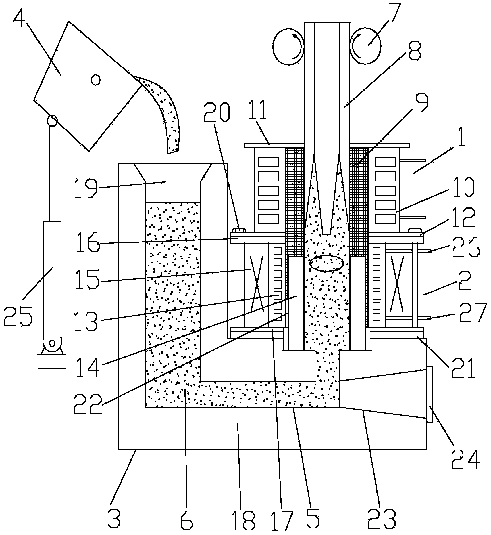
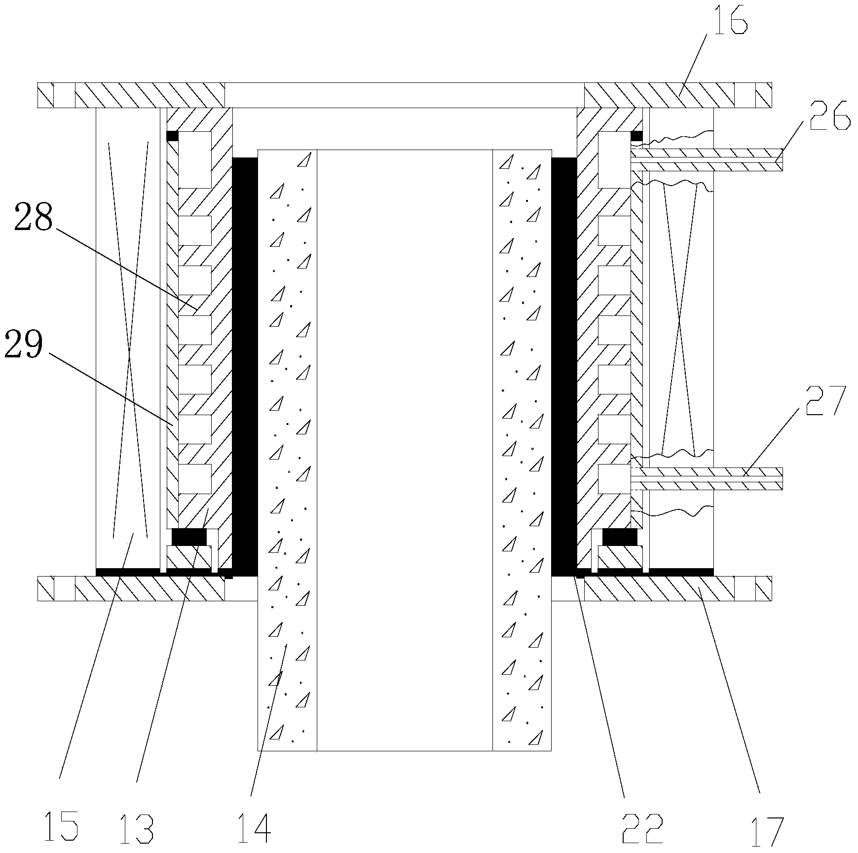
[0025] Attached below figure 1 , 2 An embodiment of the present invention is described.

[0026] The vertical continuous casting method of the hollow cast iron pipe adopts the L-shaped continuous casting holding furnace 3, the rotating magnetic field generator 2 and the crystallizer 1 to jointly form a U-shaped channel 5 for the circulation of the molten iron 6, and the molten iron 6 in the molten iron pouring ladle 4 flows from the L-shaped Continuous injection is made at the entrance of the left end of the U-shaped channel 5 of the continuous casting holding furnace 3, flows through the rotating magnetic field generator 2 and then enters the crystallizer 1, and the rotating magnetic field generated by the rotating magnetic field generator 2 drives the molten iron 6 surrounded by the magnetic field to rotate at a high speed, driving crystallization The molten iron 6 in the mold 1 rotates, and the high-speed rotating molten iron 6 is condensed from the outside to the inside o...


PUM


Abstract

Provided are a hollow cast iron tubular product and a vertical continuous casting method and special equipment thereof. An L-shaped continuous casting holding furnace, a rotating magnetic field generator and a crystallizer are connected in series to form a U-shaped channel for molten iron to flow. The rotating magnetic field generator is utilized for enabling the molten iron to rotate in the crystallizer. The produced hollow cast iron tubular product is smooth in appearance. The wall surface of the inner hole is free of hoop rings and is smooth, the internal texture is fine, the size accuracy is greatly improved, the radial growth of a primary dendritic crystal is disturbed, the proportion of an isometric crystal area is increased, the mechanical property of a hollow cast tube is improved, and the practical value is high.

Description

technical field [0001] The invention belongs to the technical field of thermal processing of metal materials, and in particular relates to a hollow cast iron pipe, its vertical continuous casting method and special equipment. Background technique [0002] Up to now, the relevant patented technologies for drawing cast iron hollow cast pipes have been disclosed, and their technical features are divided into two categories: the first category is the horizontal continuous casting scheme: one is the device and its production process for producing cast iron pipes by horizontal continuous casting method, publication number : CN1410188; the second is hollow cast iron profiles and horizontal continuous casting device, publication number: CN2589125; the third is a continuous casting production device for hollow cast iron profiles, publication number: CN102228963A. The common feature of the above technical solutions is that on the basis of horizontal continuous casting, an inner core m...

Claims


Application Information

Patent Timeline
IPC IPC(8): B22D11/14B22D11/00
CPCB22D11/006B22D11/145
Inventor 许旸邓开金
Owner SHAN XI TONGXIN LIANZHU PIPE IND
Why Eureka
Eureka Blog
Learn More