Converter gas mass-energy conversion and CO2 cycle steelmaking method

A converter gas and CO2 technology, applied in the manufacture of converters, furnaces, furnace components, etc., can solve the problem of low power consumption, achieve the effects of reducing CO2 emissions, realizing circular economy, and reducing oxidation and evaporation

Inactive Publication Date: 2014-05-07
PEKING UNIV
View PDF3 Cites 9 Cited by
  • Summary
  • Abstract
  • Description
  • Claims
  • Application Information

AI Technical Summary

Problems solved by technology

The investment of the dry system is about 12-15% higher than that of the wet system; however, there is no need to build sewage treatment facilities,

Method used


Image

  • Converter gas mass-energy conversion and CO2 cycle steelmaking method

Examples


Embodiment Construction

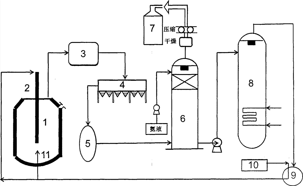
[0021] 1. For the 120t converter slag splash protection process, the adsorption device is used to recover and separate the CO in the converter gas 2 and foreign CO 2 as CO 2 Air source for top blowing, bottom blowing and slag splashing. During top blowing, O 2 Mixed with 0.1% ~ 30% CO 2 When splashing slag, use the converter oxygen lance to switch and blow CO into the furnace 2 , the amount of carbon is 30~350kg, and the gas flow rate is 50000~60000Nm 3 / h, the working pressure of the gas is 0.7~0.9MPa. CO gas collected and enriched in converter gas can be used as an important energy source for metallurgy and can be used for waste heat air of hot blast stoves, coke ovens, power plant boilers, and steel rolling heating furnaces.

[0022] 2. For the 300t converter slag splash protection process, the adsorption device is used to recover and separate the CO in the converter gas 2 and foreign CO 2 as CO 2 Air source for top blowing, bottom blowing and slag splashing. Duri...


PUM


Abstract

The invention relates to a method for converter gas CO2 separation and recycling, belongs to the field of ferrous metallurgy and greenhouse gas emission reduction, and provides an energy-saving technology for improving gas mass-energy and reducing CO2 emission. The method for converter gas CO2 separation and recycling is characterized in that high temperature gas discharged from a converter firstly enters a high-temperature waste heat recovery system for high-temperature sensible heat utilization, is conveyed to a low-temperature waste heat recovery system for waste-heat utilization after passing through a high-temperature flue gas ceramic filtering dedusting system. Then, the converter gas is conveyed to a CO2 absorption system, CO2 is absorbed and absorption liquid rich in CO2 is obtained, the CO2-removed converter gas is rich in CO which can be used as significant energy for metallurgy and can be used for hot blast heater waste heat air, coke oven, power station boiler, steel rolling heating furnace and the like, CO2-absorbed solution is desorbed by a CO2 separation system for CO2 separation, and the separated CO2 and external CO2 are circularly used for convertor slag splashing protection, bottom blowing and top blowing, recycling of the convertor gas in a workshop can be achieved, the utilization rate of the convertor gas can be improved, the emission of CO2 can be reduced, and significant social and environmental benefits can be obtained.

Description

technical field [0001] The invention belongs to the fields of iron and steel metallurgy and greenhouse gas emission reduction, relates to an energy-saving and emission-reduction technology in the iron and steel production process, and provides a CO 2 Separation, recovery, and recycling methods can improve gas energy and reduce CO 2 emission. Background technique [0002] Energy and environmental issues are becoming the focus of global and regional attention, and the issue of greenhouse gas emissions has been brought to the forefront. The iron and steel industry is a traditional industry with high logistics, high energy consumption, and high pollution, and it is an industry that focuses on energy conservation and emission reduction. From the perspective of industries that produce carbon dioxide, about 50% of carbon dioxide emissions come from industrial production, among which carbon dioxide emissions from the thermal power generation industry rank first, and carbon dioxide...

Claims


Application Information

Patent Timeline
IPC IPC(8): F27D17/00C21C5/40
CPCY02P10/122Y02P10/25Y02P20/10
Inventor 袁章福吴燕潘贻芳吴湖徐秉声侯葵
Owner PEKING UNIV
Why Eureka
Try Eureka