Confocal optical scanner

A confocal and scanner technology, applied in the field of biomedical microscopic imaging, can solve the problems of slow scanning speed, uneven illumination intensity, scanning line interference, etc. The effect of uneven brightness and darkness of the image, simple installation and adjustment

Inactive Publication Date: 2014-05-07
赖博
View PDF4 Cites 21 Cited by
  • Summary
  • Abstract
  • Description
  • Claims
  • Application Information

AI Technical Summary

Problems solved by technology

[0006] The purpose of the present invention is to improve the deficiencies existing in various confocal optical scanners, such as slow scanning speed and low sensitivity of single-point confocal laser scanners; rotary disk confocal scanners have bright and dark scanning line interference , uneven illumination intensity; slow scanning speed of the slider confocal scanner, etc., a new multi-pinhole confocal optical scanner is provided, which is combined with a fluorescence microscope and an area array detector to form a confocal imaging system, thereby obtaining high-speed High quality confocal images

Method used


Image

  • Confocal optical scanner
  • Confocal optical scanner
  • Confocal optical scanner

Examples


Embodiment 1

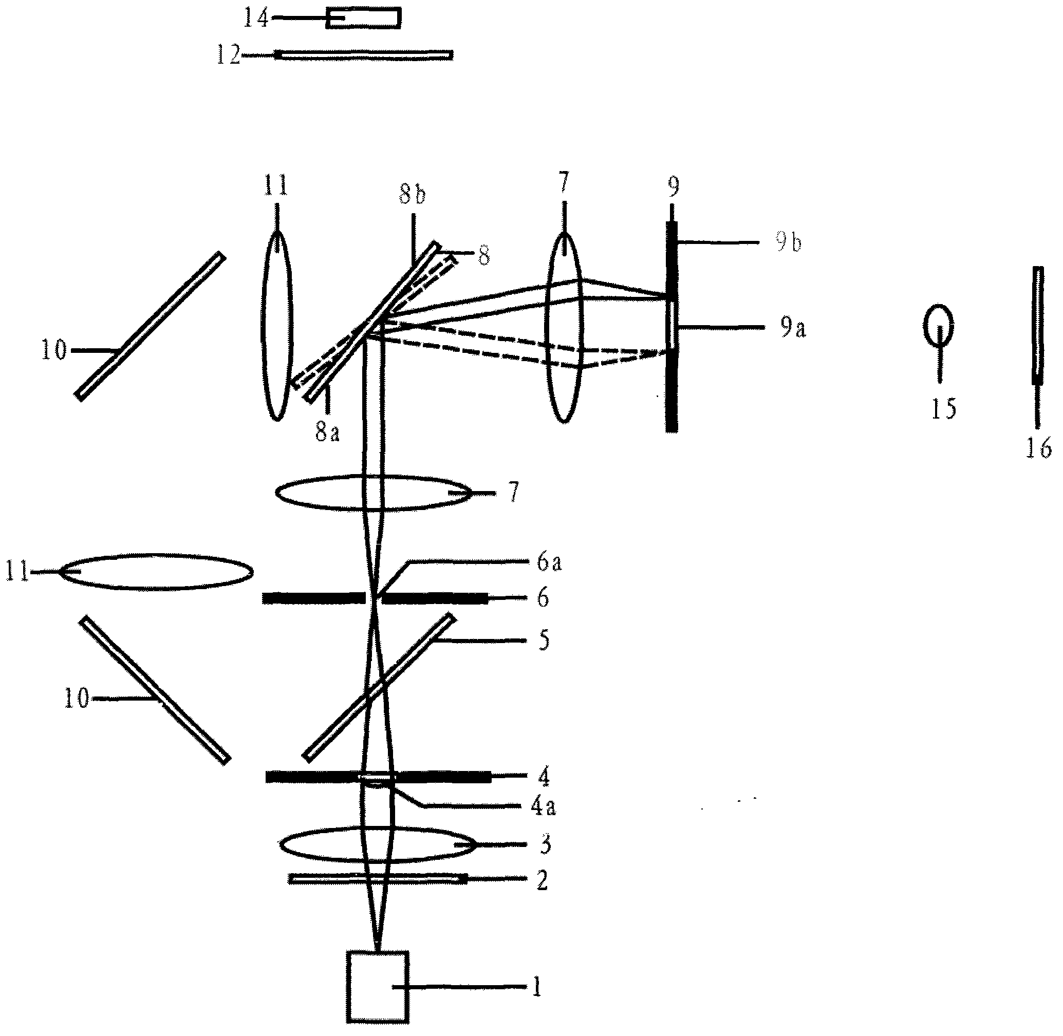
[0052] Figure 2a and 2b It is a schematic diagram of the first confocal optical scanner related to the present invention, wherein the first reflection surface 8a, the second reflection surface 8b of the scanning galvanometer 8 and the total reflection mirror group 10 are all plane reflections.

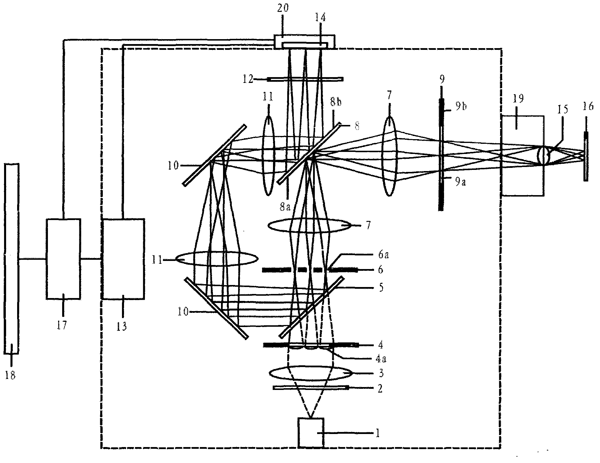
[0053] like Figure 2a , in this embodiment, before the area array detector 20 (not shown) starts to expose, the controller 13 (not shown) controls the scanning vibrating mirror 8 to stay in the forward or reverse maximum rotation angle position; the light from the light source 1 Emitted, through the excitation color filter 2, the illumination lens group 3, the microlens 4a on the microlens array 4, the dichroic beam splitter 5 and the pinhole 6a on the pinhole array 6 to form a plurality of excitation point light sources; The image is imaged by the delay lens group 7 and reflected by the first reflective surface 8a of the scanning galvanometer 8 on the opaque portion 9b of the cut-...

Embodiment 2

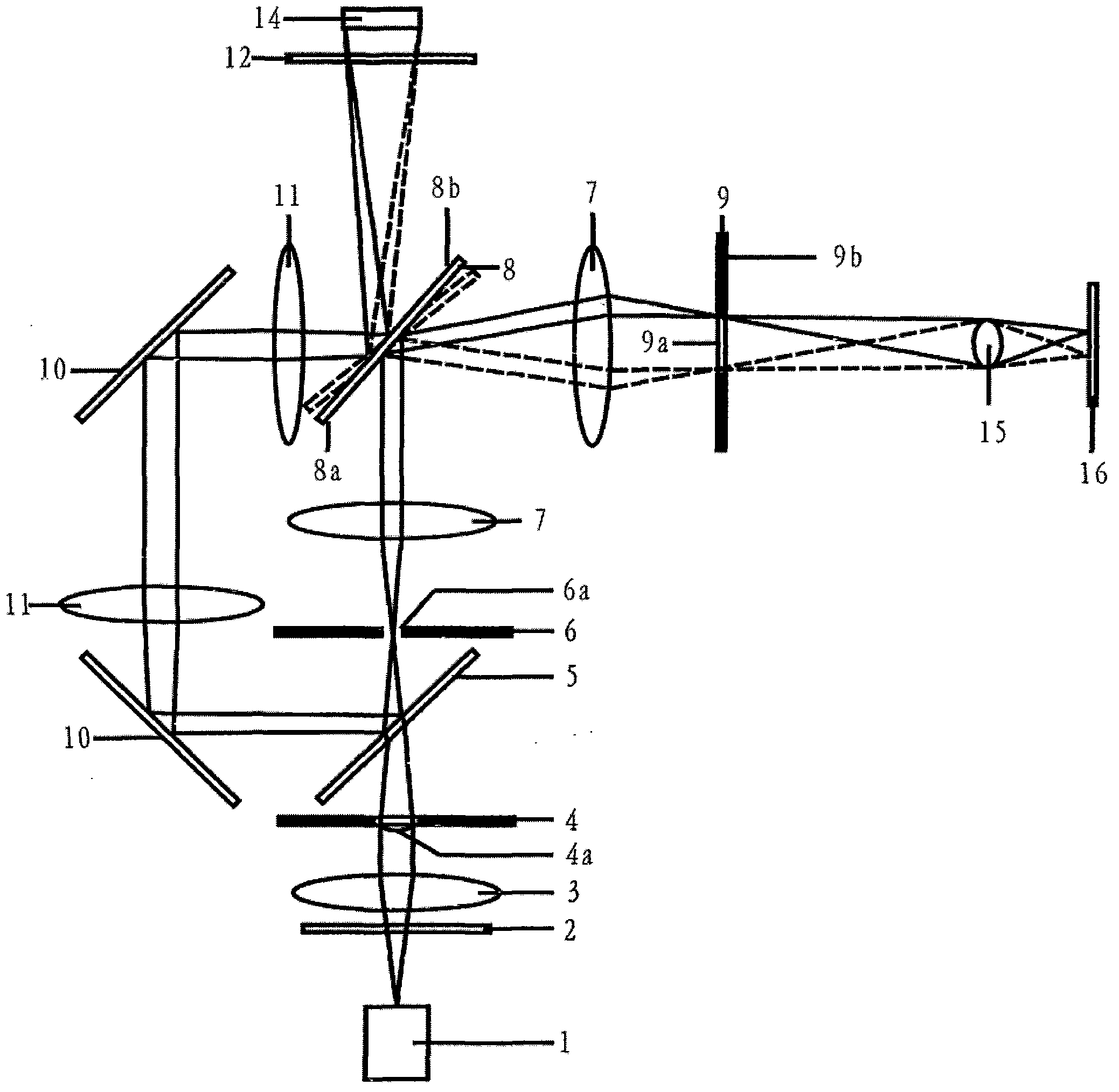
[0058] image 3 It is a schematic structural diagram of the second confocal optical scanner related to the present invention, and the difference from Embodiment 1 is as follows: the first reflective surface 8a, the second reflective surface 8b, and the first reflective surface 8a of the scanning galvanometer 8 The total reflection mirror 10 between the pinhole array 6 is a concave reflection, which can replace the delay lens group 7 and the imaging lens group 11 of the embodiment 1 to image the pinhole array 6, the first reflective surface 8a and the first reflective surface The imaging magnification of the total reflection mirror 10 between 8a and the pinhole array 6 is M2. Because the delay lens group 7 and the imaging lens group 11 are reduced, there are fewer optical interfaces in the optical path of this embodiment, and higher light efficiency can be obtained.

Embodiment 3

[0060] Figure 4 It is a schematic structural view of the third confocal optical scanner related to the present invention, and the difference from Embodiment 2 is as follows: the first reflection surface 8a of the scanning galvanometer 8 and the total reflection mirror group 10 are concave reflection, the second reflection Surface 8b is planar reflection.


PUM


Abstract

The invention relates to a confocal optical scanner, and especially relates to a confocal optical scanner using array detectors comprising CCD, EMCC, CMOS and sCOMS as detection units and applied to biological fluorescent microscopic imaging. The confocal optical scanner is mainly characterized in that microlenses of a microlens array corresponds to pinholes of a pinhole array one by one, and the pinhole array is positioned in the focal plane of the microlenses; excitation light illuminating a sample and fluorescence emitted by the sample pass through a same pinhole in the pinhole array; the pinholes of the pinhole array are arranged in an equidistant matrix manner, and illumination points of the pinholes on the sample have a same moving speed; and a scan vibrating mirror has two reflection planes, and the scanning imaging of the sample is realized through the reciprocating rotation of the scan vibrating mirror. So the confocal optical scanner has the advantages of fast scanning speed, zero stray light background noise, uniform illumination intensity and the like, and can be easily synchronously controlled together with the exposure of the detectors.

Description

technical field [0001] The invention relates to a multi-pinhole confocal optical scanner, in particular to a multi-pinhole confocal optical scanner which uses area array detectors such as CCD, EMCCD, CMOS and sCOMS as detection units and is applied to microscopic imaging. The invention is mainly used in the field of biomedical microscopic imaging, and can also be used in material research and integrated circuit chip detection imaging. Background technique [0002] With the deepening of cell biology research, the application of fluorescence microscopy imaging is becoming more and more common, and confocal microscopy imaging has received more and more attention. However, current confocal imaging systems have various insurmountable issues that make it difficult to further improve the performance of the system: [0003] 1. The imaging speed of single-pinhole laser confocal optical scanners is generally relatively low. Under typical 1024×1024 pixel imaging conditions, the imagin...

Claims


Application Information

Patent Timeline
Patent Type & Authority Applications(China)
IPC IPC(8): G01N21/01G01N21/64G02B26/12
Inventor 赖博
Owner 赖博
Why Eureka
Try Eureka