A low-concentration flue gas infrared analyzer and detection method based on Fourier transform
An infrared analyzer and Fourier transform technology, which is applied in the analysis of materials, material analysis by optical means, instruments, etc., can solve the problems of many interference factors in pollutant measurement, unsuitable for continuous measurement, and complex measurement system. The effect of improving response time characteristics, minimizing optical drift, and improving instrument sensitivity
- Summary
- Abstract
- Description
- Claims
- Application Information
AI Technical Summary
Problems solved by technology
Method used
Image
Examples
Embodiment 1
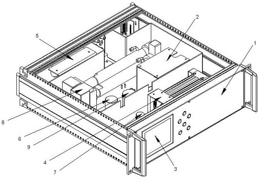
[0039] figure 1 It is a structural layout diagram of the flue gas analyzer in the embodiment of the present invention, as shown in the figure, including a chassis 1, a heating control unit 2, an output display unit 3, a data acquisition and processing unit 4, and a power supply 5; a flue gas pipe is arranged in the chassis 1 The water filter device 6 is installed at the inlet of the flue gas pipeline, and the temperature sensor, pressure sensor, humidity sensor, oxygen sensor 7, and gaseous pollutant detection unit 8 are respectively installed on the flue gas pipeline; a flue gas multi-parameter The measuring chamber 9, the temperature sensor, the pressure sensor and the humidity sensor are all set in the flue gas multi-parameter measuring chamber 9.
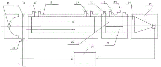
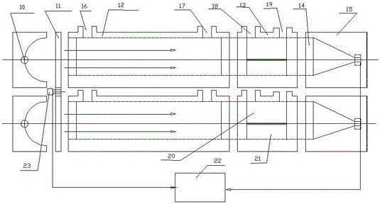
[0040] The gaseous pollutant detection unit 8 of this embodiment includes figure 2 The mid-infrared light source 10 and the shutter arranged thereafter are arranged along the optical path behind the light chopper to be an abs...
Embodiment 2
[0045] As an improvement of Embodiment 1, in this embodiment, the detection sensor 15 in Embodiment 1 is preferably a pyroelectric infrared detector, and the structure includes Figure 4 Middle pyroelectric element 24, electrode 25, external circuit wire 26, load 27, power supply 28 are composed, wherein, pyroelectric element 24 is arranged at the position facing the optical path direction at the rear of optical filter 14, and electrodes 25 are respectively located at pyroelectric On both sides of the element 24 , the external circuit wires 26 are connected in series with the load 27 and the power source 28 respectively to the electrodes 25 on both sides of the pyroelectric element 24 . In the above technical solution, the pyroelectric element 24 is preferably made of lithium tantalate crystal (TaLiO3) material, and other structures are the same as those in Embodiment 1.
[0046] figure 2 Among them, the monochromatic light emitted by the infrared light source 10 is modulate...
Embodiment 3
[0048] Adopt the detection method of the analyzer of embodiment 1, it is characterized in that comprising the steps:
[0049] Step 1. Standard gas preparation: configure NO or CO standard gas with a mass concentration of 100mg / m3, and the balance is nitrogen, to be tested;
[0050] Step 2, start-up and preheating: the infrared light source (10) emits monochromatic light, and the shutter shields the infrared light source (10) to generate two beams of light that illuminate the sample cell (20) and the reference cell (21) respectively; the first The light beam is the measurement side beam, which passes through the absorption cell (12), the sample cell (20), and the filter (14) to the detection sensor (15) in sequence; the second beam is the reference side beam, which passes through the absorption cell (12), the reference Compared with the cell (21), the filter (14) reaches the detection sensor (15);
[0051] Step 3, zero gas correction: pass zero gas into the analyzer, select ni...
PUM
| Property | Measurement | Unit |
|---|---|---|
| length | aaaaa | aaaaa |
Abstract
Description
Claims
Application Information
 - R&D
- Intellectual Property
- Life Sciences
- Materials
- Tech Scout
- Unparalleled Data Quality
- Higher Quality Content
- 60% Fewer Hallucinations
Browse by: Latest US Patents, China's latest patents, Technical Efficacy Thesaurus, Application Domain, Technology Topic, Popular Technical Reports.
© 2025 PatSnap. All rights reserved.Legal|Privacy policy|Modern Slavery Act Transparency Statement|Sitemap|About US| Contact US: help@patsnap.com


