Method and device for quickly separating optical crystals by using laser light

An optical crystal and laser technology, applied in laser welding equipment, manufacturing tools, welding/welding/cutting items, etc., can solve the problems of expensive equipment, severely restricted separation speed, complex mechanism, etc., to eliminate vibration and mechanical stress, maintain Physical properties, the effect of eliminating pollution damage

Active Publication Date: 2014-06-04
武汉飞能达激光技术有限公司
View PDF5 Cites 17 Cited by
  • Summary
  • Abstract
  • Description
  • Claims
  • Application Information

AI Technical Summary

Problems solved by technology

[0005] Although this method realizes the non-contact separation of KDP crystals, it must use an ultrafast laser to form a pretreatment surface in the crystal, and there are still the following problems: (1) The use of ultrafast lasers to modify the crystal has a negative impact on the light intensity control accuracy and Stability requirements are extremely high, the mechanism is complicated, and the equipment is expensive
(2) Making a modified surface that runs through the separation track will destroy the stability of the internal stress of the crystal, and will also form a burst point when encountering material lattice defects, and cracks often occur during the manufacturing process
(3) The pretreatment surface that runs through the crystal will destroy the roughness and material properties of the separated side wall, so that the separated crystal side wall must be polished and removed before the pretreated area can be used
(4) The separation principle of this method is the tensile stress generated by laser heating material expansion and cooling, so the separation speed is severely restricted by the cooling of the material. Although it is much faster than traditional mechanical cutting, the speed still cannot meet the actual needs.

Method used


Image

  • Method and device for quickly separating optical crystals by using laser light
  • Method and device for quickly separating optical crystals by using laser light

Examples


example 1

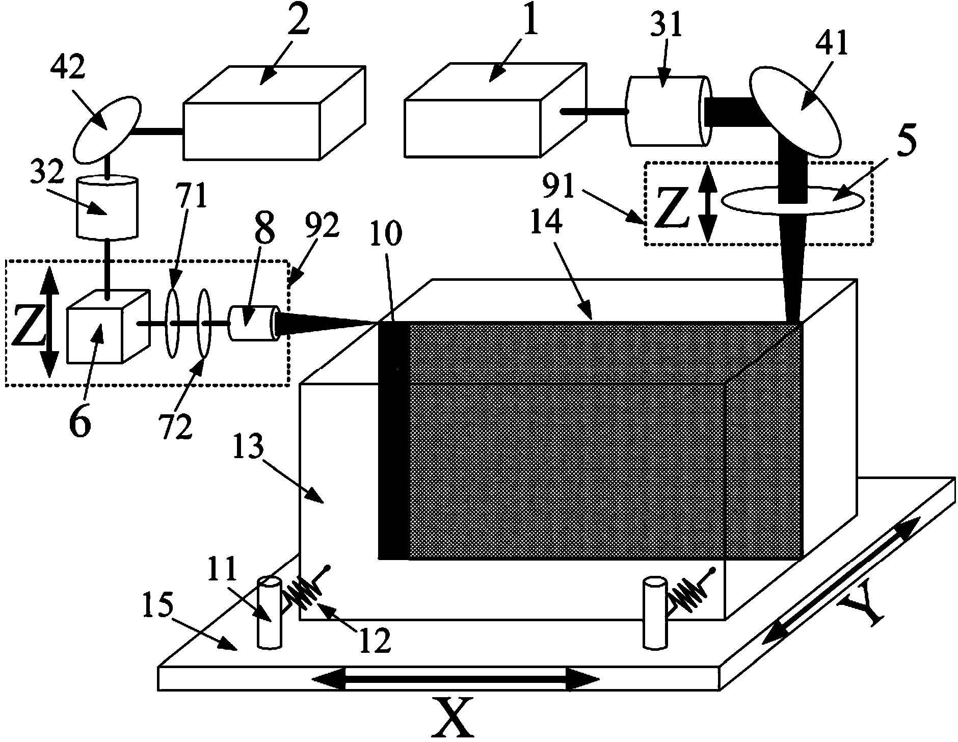
[0059] The present invention adopts a femtosecond laser with a pulse width of 518 fs, a wavelength of 1030 nm, and a maximum single pulse energy of 200 μJ as an ultrafast laser. The YLP-50 model CW fiber laser of German IPG Company is used as an ordinary high-power laser, and its maximum output average power is 50W. The focused spot diameter of the ultrafast laser is less than 5 μm, and the spot diameter of the high-power ordinary laser is about 50 μm. The separation optical crystal is KDP crystal, the pattern length is 100 mm, and the thickness is 12 mm. Experimental method: adopt the first laser rapid separation optical crystal method, adjust the single pulse energy of the ultrafast laser to 200μJ, the scanning speed of the ultrafast laser to 50mm / s, the output power of the ordinary high-power laser to 30W, and the scanning speed to 400μm / s , the moving speed is 2mm / s. Experimental results: The optical crystal is separated along the separation track, the separation side wal...

example 2

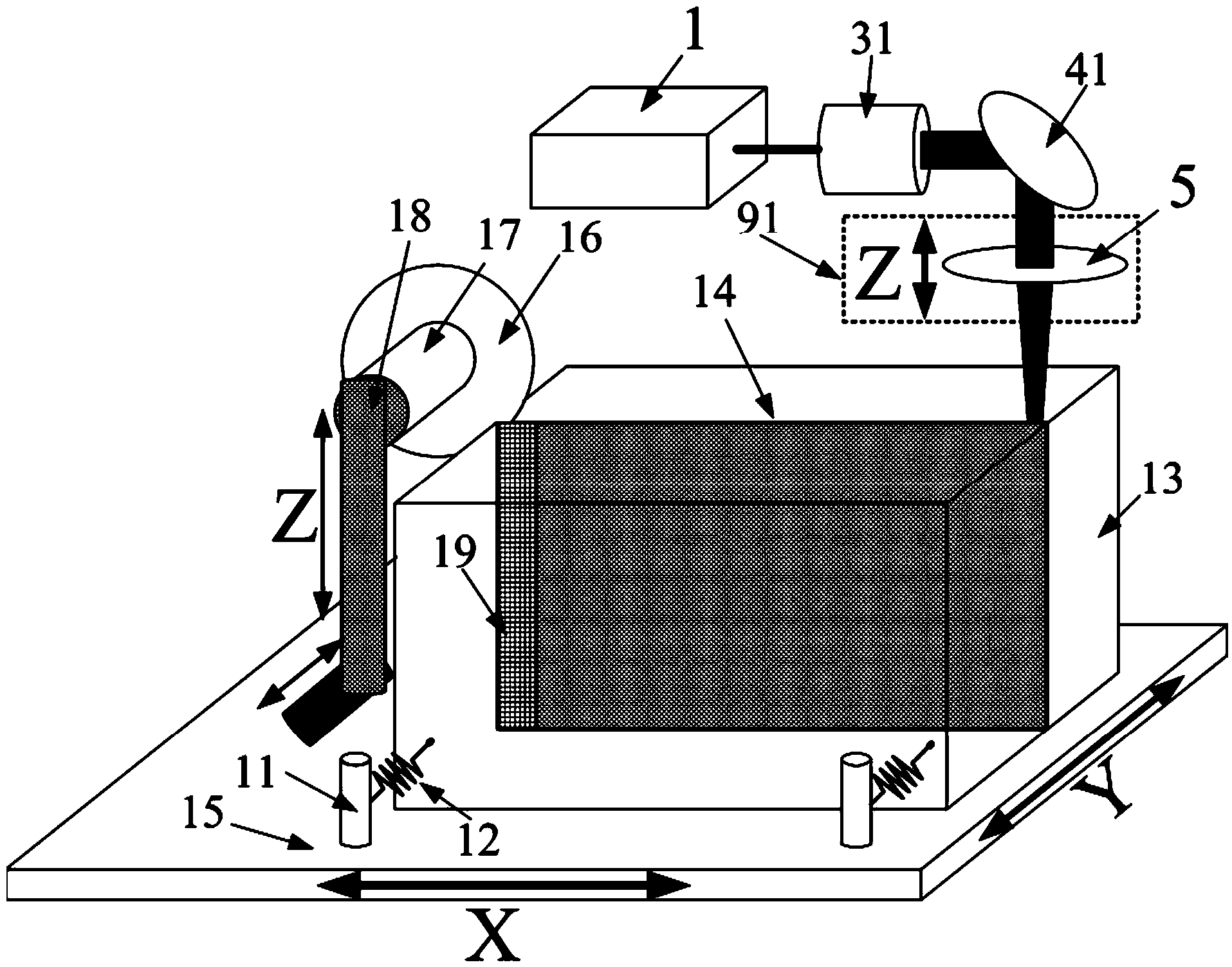
[0061]The present invention adopts a servo motor with a maximum rotational speed of 4000 rpm, the moving speed of the motor along the Z-axis guide rail is 1 mm / s, and the moving feed distance of the motor along the X-axis is 10 μm. The diameter of the micro-diamond grinding wheel is 20 mm, and the thickness of the outermost ring of the grinding wheel is 100 μm. The YLR-50 series pulsed fiber laser from German IPG company is used as a common high-power laser, the output wavelength is 1070nm, the highest average output power is 50W, and the maximum single pulse energy is 1mJ. The focus spot size of ordinary high-power laser is 30μm, the separation optical crystal is KDP crystal, the sample length is 200mm, and the thickness is 11.8mm. Test method: adopt the second method of laser rapid separation of optical crystals. Adjust the rotation speed of the servo motor to 2500 rpm, the output power of the fiber laser to 10 W, the pulse energy to 1 mJ, the scanning speed to 200 μm / s, an...

example 3

[0063] The present invention adopts a servo motor with a maximum rotational speed of 1000 rpm, the moving speed of the motor along the Z-axis guide rail is 100 μm / s, and the moving feed distance of the motor along the X-axis is 30 μm. The diameter of the micro-diamond grinding wheel is 10 cm, and the thickness of the outermost ring of the grinding wheel is 100 μm. A domestic 50W green laser is used as a common high-power laser. The focus spot size of ordinary high-power laser is 20μm, the separation optical crystal is KDP crystal, the sample length is 400mm, and the thickness is 30mm. Test method: adopt the second method of laser rapid separation of optical crystals. Adjust the rotation speed of the servo motor to 500 rpm, the output power of the laser to 40 W, the pulse energy to 1 mJ, the scanning speed to 400 μm / s, and the moving speed to 4 mm / s. Experimental results: The optical crystal is separated along the separation track, the separation side wall is smooth and flat,...


PUM

PropertyMeasurementUnit
widthaaaaaaaaaa
lengthaaaaaaaaaa
diameteraaaaaaaaaa

Abstract

The invention discloses a method for quickly separating optical crystals by using layer light. The method comprises the following steps of setting the separating direction of the optical crystals by using ultrafast laser light or a miniature diamond grinding wheel; forming a precast microcrack with the direction along a to-be-separated path at a separation starting end; performing scanning heating on the preformed microcrack by using focusing laser light to form a laser-induced microcrack; quickly moving the focusing laser light along the to-be-separated path until the laser moving speed is the same with the crack expansion speed; enabling the focusing laser light to always follow the foremost end of the microcrack; performing thermal expansion effect on materials on two sides of the microcrack; generating forward squeezing force and lateral pulling stress on the tip of the microcrack; and pulling materials of the crystals so as to realize high-quality separation of the crystals. A device comprises a microcrack preforming mechanism, a single-focus-point laser machining system and a two-dimensional worktable. By using the method and the device, the separation speed, the separation accuracy, the machining safety and the machining quality of the optical crystals can be improved, non-loss separation of the optical crystals is realized, and a quasi-polishing-level finishing separation surface is formed.

Description

technical field [0001] The invention belongs to the technical field of laser processing applications, and relates to a method for rapidly separating optical crystals by laser and a related device. The invention can utilize laser light to separate and process transparent materials quickly and with high quality, especially to separate optical crystals such as potassium dihydrogen phosphate (KDP) safely, quickly and with high quality. Background technique [0002] KDP type crystal is an important class of multifunctional crystal materials. During World War II, KDP was used to manufacture piezoelectric transducers and sonar equipment and became military supplies. Since the emergence of laser technology in the 1960s, this type of crystal material has been widely used in the field of optoelectronic technology due to its high nonlinear optical coefficient, wide light transmission band, and excellent electro-optical and frequency conversion performance. Especially in recent years, ...

Claims


Application Information

Patent Timeline
Patent Type & Authority Applications(China)
IPC IPC(8): B23K26/00
CPCB23K26/0643B23K26/38B23K26/40B23K26/702B23K2103/50
Inventor 段军邓磊敏曾晓雁
Owner 武汉飞能达激光技术有限公司
Why Eureka
Try Eureka