Hydraulic control system for constant pressure press for timber floor

A hydraulic control system and wooden floor technology, which is applied in the field of wood machinery, can solve problems such as inability to guarantee product uniformity, immature hydraulic mechanism, and cumbersome manufacturing process, and achieve good steady-state control characteristics, low power consumption, and suppression of interference Effect

Inactive Publication Date: 2014-06-11
HUZHOU NANXUN XIANGLONG WOOD FACTORY
View PDF7 Cites 10 Cited by
  • Summary
  • Abstract
  • Description
  • Claims
  • Application Information

AI Technical Summary

Problems solved by technology

Existing wood flooring is mainly divided into solid wood flooring, solid wood composite flooring and laminate flooring. These three types of wood flooring generally include veneer, core board and balance layer from top to bottom. The existing wood flooring manufacturing process is divided into multiple In the process, the two sides of the slab are first processed to obtain grooves, and then the skin is attached to the surface of the slab and hot-pressed, and then the balance paper is attached to the bottom of the slab and hot-pressed, so the production of the existing wooden floor The process is not only cumbersome, the production efficiency is not high, and it is a waste of manpower, but also generally manual operation, which cannot guarantee product uniformity
At present, the industry is researching a system that realizes a constant pressure floor by controlling the feedback control of the hydraulic mechanism and the motor and other mechanical mechanisms of the pressing speed of the upper cylinder, but the current research on the hydraulic mechanism is relatively immature, so the existing The hydraulic mechanism has become an urgent problem to be solved in this field

Method used


Image

  • Hydraulic control system for constant pressure press for timber floor
  • Hydraulic control system for constant pressure press for timber floor
  • Hydraulic control system for constant pressure press for timber floor

Examples


Embodiment

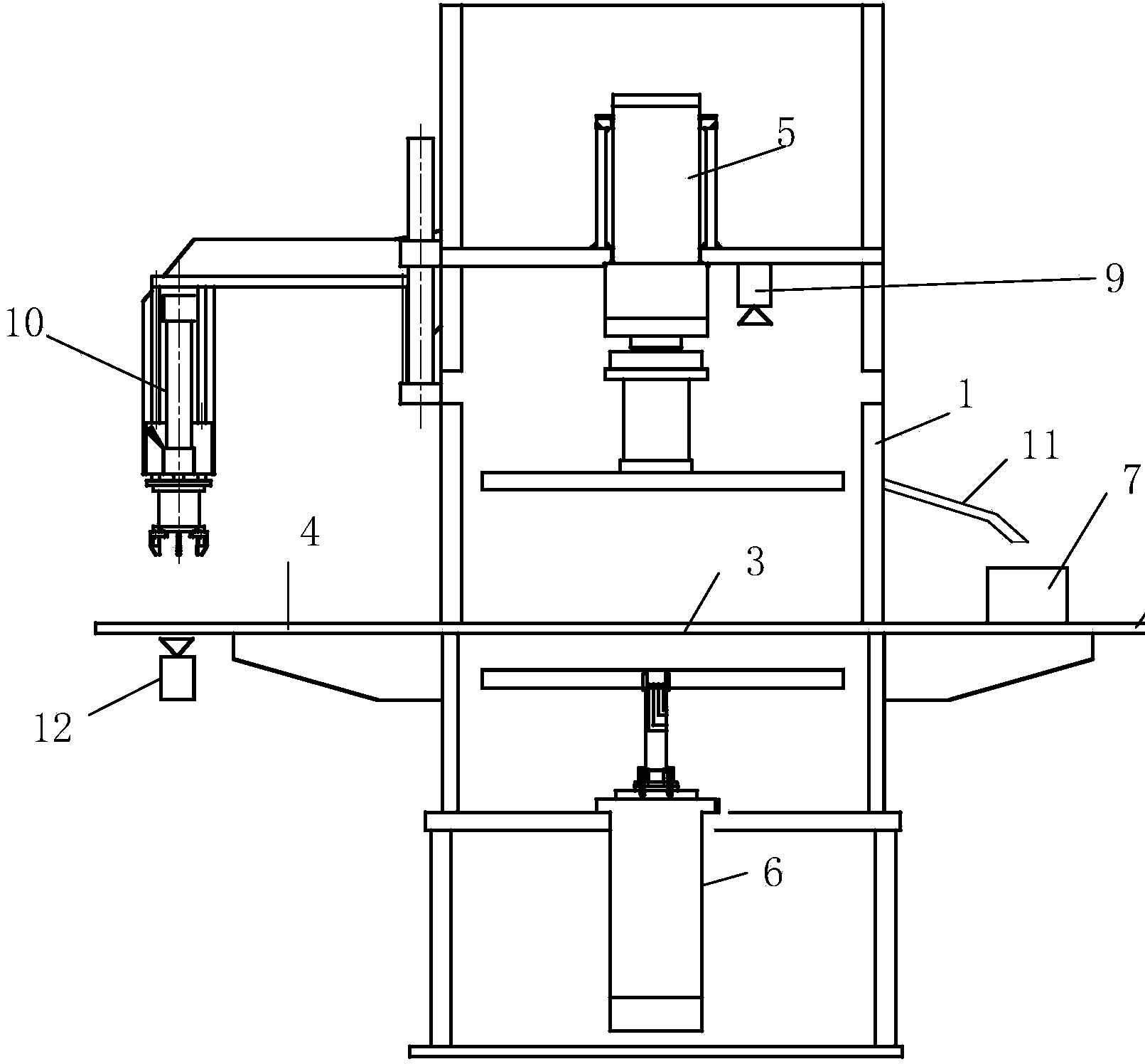
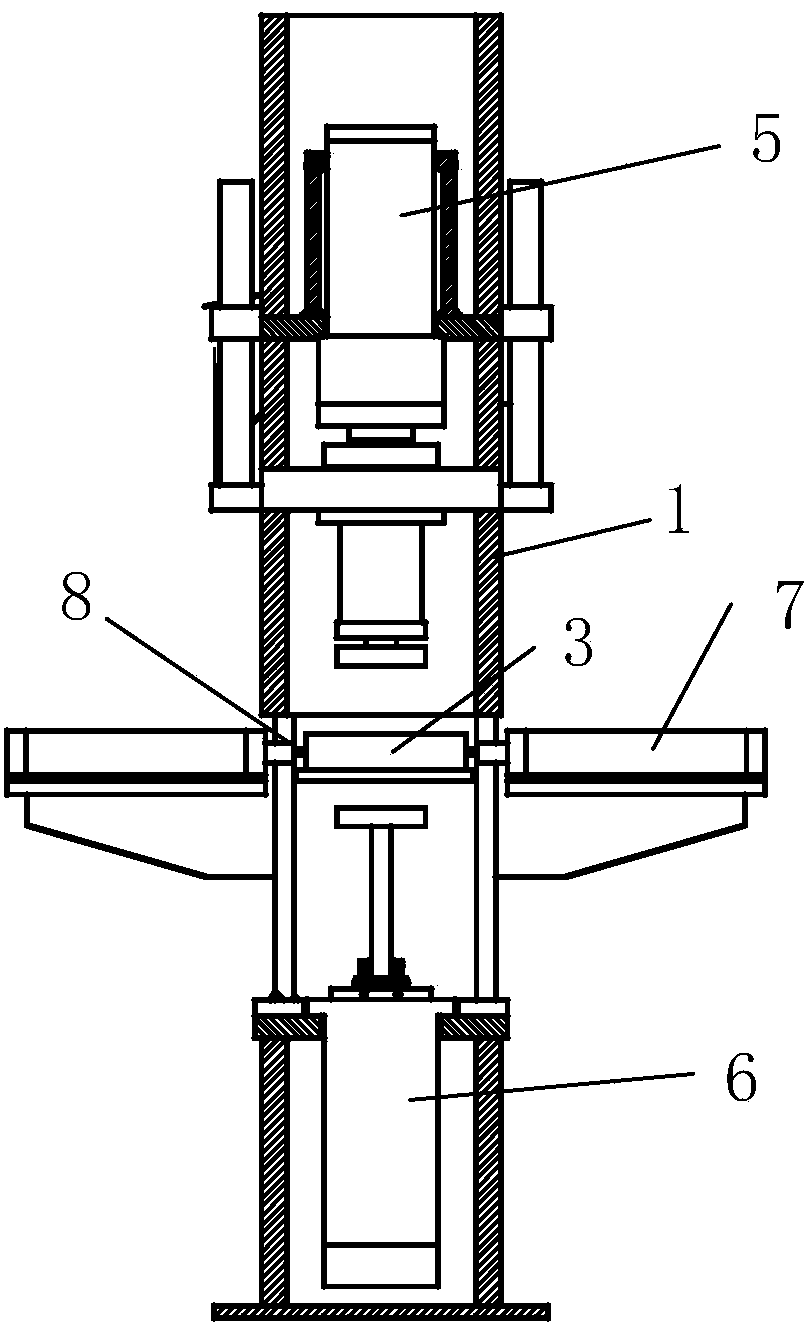
[0023] Example: a hydraulic control system for a constant pressure press on a wooden floor, such as figure 1 and figure 2 As shown, it includes a frame 1. The middle of the frame 1 is sequentially provided with a feeding conveyor belt 2, a working conveyor belt 3 and a discharging conveyor belt 4 from front to back. The feeding conveyor belt and the discharging conveyor belt are always at a fixed speed. The working conveyor belt runs at different speeds through the induction device; the top of the working conveyor belt 3 has a lower pressure cylinder 5, and the bottom of the working conveyor belt 3 has an upper pressure cylinder 6; the two sides of the working conveyor belt 3 are also A tongue-and-groove cutting cylinder 7 is provided, and the extension end of the tongue-and-groove cutting cylinder 7 is provided with a tongue-and-groove cutting tool head 8; an infrared sensing device 9 is also provided above the working conveyor belt 3, and the output end of the infrared sens...


PUM


Abstract

The invention discloses a hydraulic control system for a constant pressure press for a timber floor. The hydraulic control system for the constant pressure press for the timber floor comprises a mechanical mechanism and a hydraulic mechanism; a proportional control amplifier (16) of the hydraulic mechanism comprises an input interface unit (18) connected with a pressure sensor (17); the input interface unit (18) is connected with a signal processing unit (19) connected with a power amplifying unit (20); the power amplifying unit (20) is connected with a proportional speed regulation valve (15) provided with a displacement sensor (21); the displacement sensor (21) is connected with a signal conditioning circuit (22); the signal conditioning circuit (22) is connected with the signal processing unit (19). Multiple timber floor manufacturing procedures are integrated, so the manufacturing process is greatly simplified, the production efficiency is improved and manpower is saved; the hydraulic control system can be industrially produced, so the product consistency can be ensured.

Description

technical field [0001] The invention relates to a hydraulic control system for a wood floor constant pressure press, belonging to the field of wood machinery. Background technique [0002] Wood flooring is an indispensable home improvement material in home decoration. With the continuous improvement of living standards, consumers have higher and higher requirements for flooring. Existing wood floors are mainly divided into solid wood floors, solid wood composite floors and laminate floors. These three kinds of wood floors generally include veneer, core board and balance layer from top to bottom. The production process of existing wood floors is divided into multiple layers. In the process, the two sides of the blank board are first processed to obtain a tongue and groove, and then the skin is pasted on the surface of the blank board and hot-pressed, and then the balance paper is pasted on the bottom surface of the blank board and hot-pressed. Therefore, the production of the...

Claims


Application Information

Patent Timeline
IPC IPC(8): F15B11/04F15B13/02B27D3/00
Inventor 吴国权
Owner HUZHOU NANXUN XIANGLONG WOOD FACTORY
Why Eureka
Try Eureka