Oxygen-enriched nitrogen supply system for cupola furnace

A supply system, cupola technology, applied in the direction of oxygen preparation, furnace, vertical furnace, etc., can solve the problems of waste of energy and resources, inability to make full use of nitrogen, not easy to burn, full use of nitrogen, waste, etc., to save costs and reduce coke Billy, the effect of raising the combustion temperature

Active Publication Date: 2014-06-18
济南市平阴县玛钢厂
View PDF14 Cites 2 Cited by
  • Summary
  • Abstract
  • Description
  • Claims
  • Application Information

AI Technical Summary

Problems solved by technology

At present, in the oxygen-enriched preparation and supply technology, independent PSA (pressure swing adsorption), VPSA (vacuum pressure swing adsorption) and membrane separation air oxygen production and supply devices are mainly installed in front of the blast furnace blower, whether it is PSA or membrane separation The air oxygen generator can only prepare and use one of the gases. If oxygen is used, it is called an oxygen generator, and if nitrogen is used, it is called a nitrogen generator. It is a waste of another gas, resulting in a waste of energy and resources.
Chinese patent document CN202849472U discloses an oxygen-enriched dry gas supply device for blast furnace ironmaking, which can only provide a supply device for producing oxygen-enriched dry gas required for blast furnace smelting, and cannot make full use of the non-combustible characteristics of nitrogen to produce Nitrogen gas discarded in the oxygen enrichment process is used as the bag dust removal gas in the cupola to realize full utilization of nitrogen gas

Method used


Image

  • Oxygen-enriched nitrogen supply system for cupola furnace

Examples


Embodiment 1

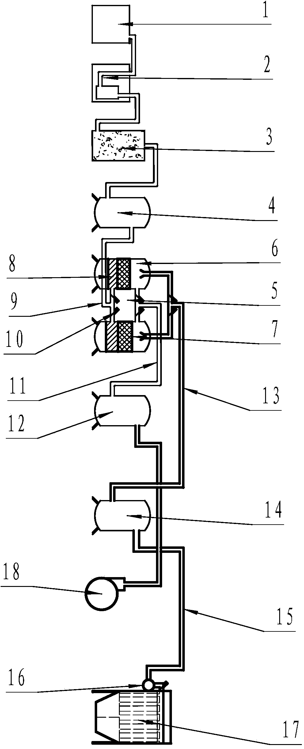
[0015] Example 1, such as figure 1 The shown oxygen-enriched and nitrogen-enriched gas supply system for cupolas includes oxygen-enriched and nitrogen-enriched gas preparation devices and oxygen-enriched and nitrogen-enriched gas supply devices. 1. Cold dryer 2, activated carbon tank 3, compressed air storage tank 4 and oxygen-generating and nitrogen-generating unit 5. The oxygen-generating and nitrogen-generating unit 5 is composed of a pair of adsorption towers 6. The bottom is equipped with activated alumina 8, and the top is equipped with zeolite molecular sieve 7. The lower part of the tower is air-tightly connected to the air pipeline 9 controlled by the solenoid valve 10, and the upper part of the tower is air-tightly connected to the oxygen output controlled by the solenoid valve 10. Pipeline 11, the other end of the oxygen output pipeline 11 is airtightly connected to the oxygen tank 12, characterized in that: the top of the adsorption tower 6 is airtightly connected,...


PUM


Abstract

The invention discloses an oxygen-enriched nitrogen supply system for a cupola furnace. The oxygen-enriched nitrogen supply system comprises an oxygen-enriched nitrogen preparation device and an oxygen-enriched nitrogen supply device, and is characterized in that the tower top of an adsorption tower is connected with a nitrogen output pipeline of which one end extends into a tower body of the adsorption tower and the other end is connected with a nitrogen tank; an electromagnetic valve is arranged at a position, which is close to the tower top of the adsorption tower, of the nitrogen output pipeline; the nitrogen supply device consists of a nitrogen supply pipeline of which one end is connected with the nitrogen tank and the other end is connected with a cupola furnace dust removal device, and an electromagnetic valve and a nitrogen storage bag which are arranged on the nitrogen supply pipeline close to the cupola furnace dust removal device. The oxygen-enriched nitrogen supply system for the cupola furnace has the beneficial effects that waste nitrogen in the conventional cupola furnace oxygen-enriched air supply technology is conveyed into the cupola furnace and is used as power gas for a cupola furnace dust removal system, so that the phenomenon of bag burning caused by a fact that the conventional cupola furnace dust removal system uses air is avoided, and continuous work of the cupola furnace dust removal system is realized; the expense on dust removal bags is saved by about 100,000 RMB all the year round.

Description

technical field [0001] The invention belongs to the cupola ironmaking auxiliary system, in particular to a supply system for directly making compressed air into oxygen-enriched and nitrogen-enriched gas for the cupola. Background technique [0002] The performance of the cupola is very important to the quality and cost of castings. The cupola oxygen-enriched air supply technology for traditional smelting equipment in the foundry industry refers to the use of oxygen-enriched combustion-supporting methods to fully burn the coke in the cupola, improve the smelting intensity and the tuyere zone of the hearth. Combustion temperature, thereby increasing blast furnace output and reducing coke ratio. Cupola bag dust removal is also a relatively advanced dust removal system in the foundry industry. The existing dust removal system uses air as the gas to vibrate the bag, and the oxygen and dust contained in the air often cause the bag to burn. At present, in the oxygen-enriched prepa...

Claims


Application Information

Patent Timeline
Patent Type & Authority Applications(China)
IPC IPC(8): F27B1/10F27D7/02C01B13/02C01B21/04
Inventor 董家岩董宜胜展恩振
Owner 济南市平阴县玛钢厂
Why Eureka
Try Eureka