
Preparation and energy recycling system of coal-bed gas hydrate

A technology of energy recovery and hydrate, which is applied in the direction of gas fuel, petroleum industry, fuel, etc., and can solve the problem of high recovery cost

Active Publication Date: 2014-06-25
ANHUI UNIV OF SCI & TECH
View PDF4 Cites 12 Cited by
  • Summary
  • Abstract
  • Description
  • Claims
  • Application Information

AI Technical Summary

Problems solved by technology

[0005] An object of the present invention is to provide a methane recovery system for coalbed methane hydrate in order to solve the problem of high recovery cost when extracting methane from coalbed methane hydrate. The tail gas discharged from the top is circulated and indirectly counter-currently exchanged with the initially entered coalbed methane, so as to recover its cooling capacity and achieve the purpose of reducing the initial temperature of the coalbed gas; the incompletely reacted coalbed methane discharged from the top of the hydrate reactor is circulated and The coalbed methane that enters initially is mixed and directly exchanged heat, so as to recover its cooling capacity and reduce the initial temperature of the coalbed gas; the methane saturated absorption liquid discharged from the lower end of the hydrate reactor is indirect contact with the absorption liquid from the decomposer in countercurrent, thereby Recover the cold energy in the saturated absorption liquid, and achieve the purpose of reducing the temperature of the circulating absorption liquid

Method used


Image

  • Preparation and energy recycling system of coal-bed gas hydrate

Examples


Embodiment 1

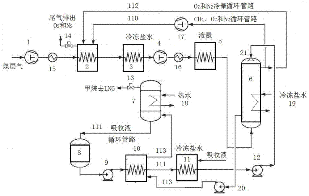
[0013] figure 1 It is a schematic flow diagram of the coalbed methane hydrate separation and capacity recovery system (example), in which 110 is the unabsorbed coalbed methane circulation pipeline, 1 is the gas pump, 2 is the heat exchanger, 3 is the refrigerant (frozen brine) cooler, 4 is Air pump, 5 is a refrigerant (liquid nitrogen) cooler, 6 is a hydrate reactor, 7 is a hydrate decomposer, 111 is an absorption liquid circulation pipeline, 8 is an absorption liquid storage tank (the absorption liquid contains 15-30 mass percent % tetrahydrofuran aqueous solution). 9 is the absorption liquid circulation pump, 10 is the heat exchanger, 11 is the refrigerant (frozen brine) cooler, 12 is the absorption liquid circulation pump, 112 is the tail gas cold recovery circulation pipeline, 13 is the methane (high concentration) gas discharge valve , 14 is the tail gas (including nitrogen, oxygen, etc.) discharge valve, 113 is the saturated absorption liquid recovery cooling capacity p...


PUM


Abstract

The invention provides a preparation and energy recycling system of coal-bed gas hydrate. The preparation and energy recycling system comprises a coal-bed gas booster pump, a refrigerant heat exchanger, a tail gas cooling capacity recycler, an un-reacted coal-bed gas cooling capacity recycler, a hydrate reactor, a hydrate decomposer, a saturated absorption liquid cooling capacity recycler, an absorption liquid circulating pump, and the like. A coal-bed gas is pressurized, cooled by saline water and liquid nitrogen through multiple steps; the coal-bed gas is ventilated from the bottom of the reactor to carry out countercurrent contact reaction with the adsorption liquid sprayed from the top of the reactor; saturated methane adsorption slurry is pumped into the decomposer by a discharging pump from the lower part of the reactor; the saturated absorption slurry carries out countercurrent indirect heat exchange with the absorption liquid entering the decomposer, and is re-pumped into the hydrate reactor after being cooled by the saline water; and methane discharged by the hydrate decomposer through a vent valve enters an LNG (liquefied natural gas) production system. Production cost of extracting methane from the coal-bed gas hydrate is greatly lowered by recycling the cooling capacity in the tail gas exhaustion gas, the cooling capacity in the un-reacted coal-bed gas, and cooling capacity in the statured absorption liquid.

Description

technical field [0001] The invention relates to a coalbed gas hydrate separation methane and energy recovery system device, belonging to the technical field of coalbed gas hydrate preparation and energy recovery and utilization. Background technique [0002] my country has abundant coalbed methane resources, and it is estimated that the amount of coalbed methane resources buried within 2000m is about 30-35×10 12 m 3 . With the development of technology and the reduction of mining costs, the development of coalbed methane is rapidly developing towards large-scale and industrialization, gradually forming an annual output of 200-300×10 8 m 3 production capacity. With the continuous expansion of the scale of coalbed methane development, traditional industrial technology directly affects the formation of the coalbed methane industry chain and has become the bottleneck of the development of the coalbed methane industry. New technologies such as hydrate technology are used to p...

Claims


Application Information

Patent Timeline
IPC IPC(8): C10L3/08
Inventor 鲁伊恒陈颖马双春冯文权魏风
Owner ANHUI UNIV OF SCI & TECH
Learn More