
Piston

A technique for pistons and heat-conducting coatings, applied in the direction of pistons, pressure inorganic powder coating, superimposed layer coating, etc., can solve the problems of uneven heat distribution and difficulties in the upper structure

Inactive Publication Date: 2014-06-25
MAHLE INT GMBH
View PDF10 Cites 4 Cited by
  • Summary
  • Abstract
  • Description
  • Claims
  • Application Information

AI Technical Summary

Problems solved by technology

However, the heat distribution in the superstructure is very inhomogeneous, as a result of which not only heat stresses are generated in the pistons, but also optimal heat dissipation through the cooling fluid circulating in the cooling pipes at least becomes difficult

Method used


Image

  • Piston
  • Piston
  • Piston

Examples


Embodiment Construction

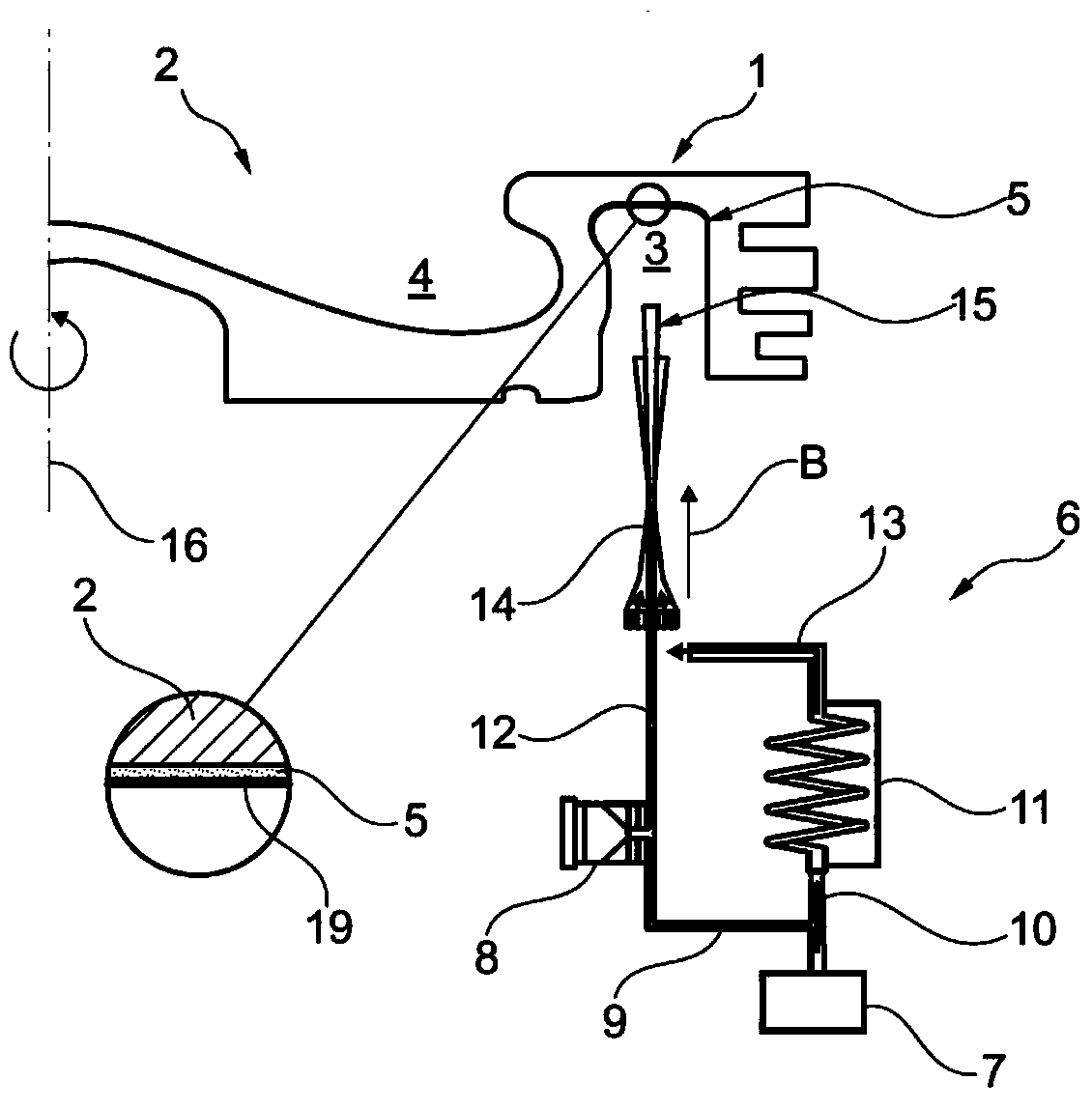
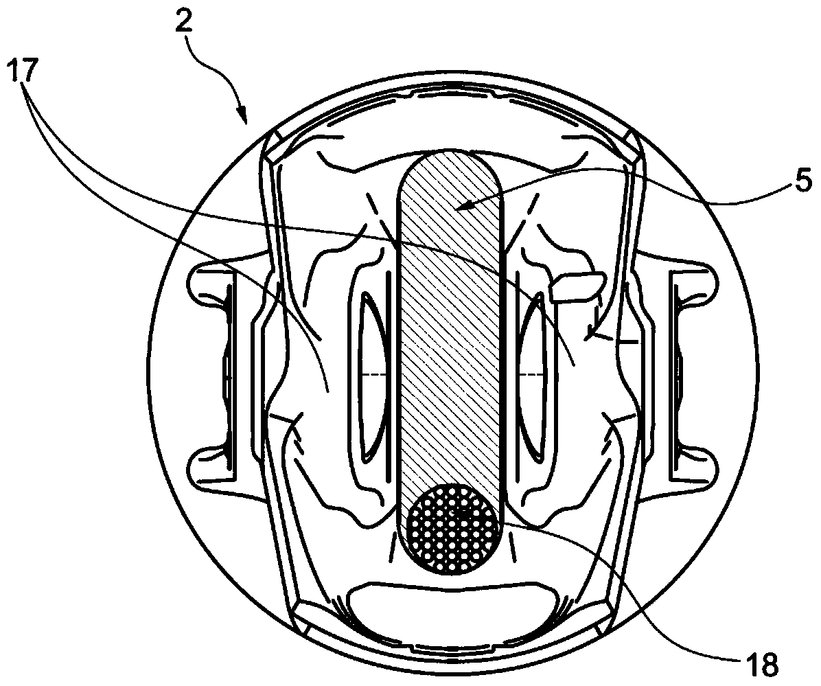
[0017] figure 1 A superstructure 1 of a piston 2 is shown, wherein cooling ducts 3 are arranged in the piston superstructure 1 . In the exemplary embodiment shown in the figures, a cooling duct 3 facing the combustion chamber 4 is arranged on the crankshaft-side piston 2 which has a heat-conducting coating 5 applied thereto by thermal spraying. One can consider melt spraying, arc spraying, plasma spraying, flame spraying, detonation spraying, laser spraying or cold gas spraying, all of which are thermal spraying methods. In particular, the last-mentioned cold-air spraying has high processing speeds and can thus be carried out very economically on production lines.

[0018] The piston 2 can be a composite material piston or a monolithic piston, or even an iron material, preferably stainless steel. The heat-conducting coating 5 applied by thermal spraying, preferably cold-air spraying, can comprise aluminum, silver and / or copper. As far as thermal conductivity is concerned, a...


PUM

PropertyMeasurementUnit
Maximum granularityaaaaaaaaaa
Thicknessaaaaaaaaaa
Thicknessaaaaaaaaaa

Abstract

The invention relates to a piston (2) for an internal combustion engine. It is essential to the invention that a region of the piston (2) on the crankshaft side is provided with a thermally conductive coating (5) that is sprayed on by means of a thermal spraying method. Thus, it is possible to economically apply the thermally conductive coating (5) within the production line.

Description

technical field [0001] The invention relates to a piston for an internal combustion engine according to the preamble of claim 1 . Background technique [0002] EP0035290A1 discloses a common piston for an internal combustion engine comprising an upper structure made of ferrous material and a lower structure connected to the upper structure by conventional means. A ring is placed on the underside of the superstructure and rests against the corresponding surface of the substructure, said ring enclosing the radially inner perimeter of the cooling tubes and the cooling chamber in the superstructure, the openings of the radially inner perimeter of the cooling tubes Facing the connection face, the cooling chamber in the superstructure is connected to the cooling pipes via radially arranged coolant holes, the openings of which face the connection face. In order to be able to increase the cooling effect of the hottest areas of the superstructure and to regulate the temperature dist...

Claims


Application Information

Patent Timeline
IPC IPC(8): F02F3/10
CPCF02F3/10C23C4/121C23C4/127C23C24/04C23C28/023C23C4/08C23C4/02F05C2251/048C23C4/123C23C4/134
Inventor 克里斯托弗·贝伦斯迪特尔·埃姆里希克里斯托弗·卢维恩乌韦·莫尔赖因哈德·罗泽
Owner MAHLE INT GMBH
Learn More