Method for producing infrared radiation reflecting film

A manufacturing method, infrared technology, applied in chemical instruments and methods, sputtering plating, ion implantation plating, etc., can solve the problems of reduced productivity, complicated equipment, increased film production times, etc., to improve the film production rate, Effects of improving productivity and improving adhesion

Inactive Publication Date: 2014-08-06
NITTO DENKO CORP
View PDF7 Cites 9 Cited by
  • Summary
  • Abstract
  • Description
  • Claims
  • Application Information

AI Technical Summary

Problems solved by technology

However, when the metal primer layer is formed into a film, the complexity of the equipment due to the increase in the number of film forming targets at the time of forming the metal reflective layer, and the decrease in productivity due to the increase in the number of film forming, etc.
In addition, since the visible light transmittance of metals such as Ni-Cr is low, there is a problem that the visible light transmittance of the infrared reflective substrate decreases.

Method used


Image

  • Method for producing infrared radiation reflecting film
  • Method for producing infrared radiation reflecting film
  • Method for producing infrared radiation reflecting film

Examples


Embodiment 1

[0133] Formation of hard coat at substrate

[0134] On one side of a polyethylene terephthalate film (manufactured by TORAY INDUSTRIES, INC., trade name "Lumirror U48", visible light transmittance: 93%) with a thickness of 50 μm, an acrylic ultraviolet curing type is formed with a thickness of 2 μm Hard coating (manufactured by Nippon Soda, NH2000G). Specifically, a hard coat solution was applied by a gravure coater, dried at 80°C, and then irradiated with a cumulative light intensity of 300mJ / cm by an ultra-high pressure mercury lamp. 2 UV light for curing.

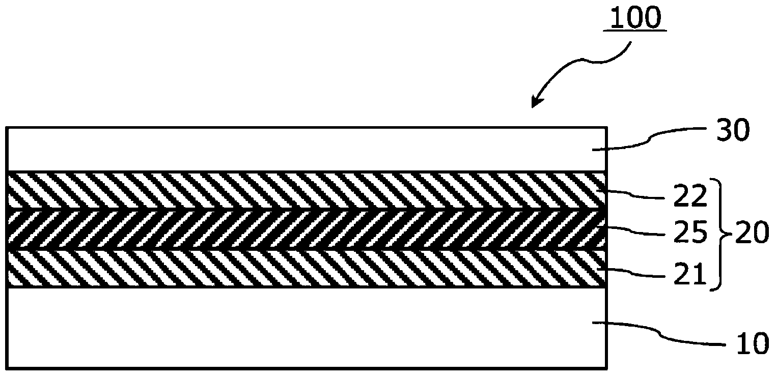
[0135] Formation of infrared reflective layer

[0136] On the hard coat layer of the polyethylene terephthalate film substrate, an infrared reflective layer was formed using a roll-to-roll sputtering device. Specifically, a 30-nm-thick substrate-side metal oxide layer made of zinc-tin composite oxide (ZTO) and a 15-nm-thick metal oxide layer made of an Ag-Pd alloy were sequentially formed by DC magnetron sputterin...

Embodiment 2A and 2B

[0140] The amount of gas introduced into the sputtering film deposition chamber during the film formation of the metal oxide layer on the substrate side was changed to Ar:O by volume ratio. 2 =90:10 (Example 2A) and Ar:O 2 =95:5 (Example 2B). Among them, the Ar gas / O 2 The amount of gas introduced is Ar:O in the same manner as in Example 1 2 =98:2. An infrared reflective film was produced in the same manner as in Example 1, except that the amount of gas introduced during film formation of the substrate-side metal oxide layer was changed as described above.

Embodiment 3

[0142] As a sputtering target for forming the metal oxide layer on the base material side and the surface side, a target obtained by sintering zinc oxide:tin oxide:metal zinc powder at a weight ratio of 19:73:8 was used. Except for this, it carried out similarly to Example 1, and produced the infrared reflection film.


PUM

PropertyMeasurementUnit
electrical resistivityaaaaaaaaaa
thicknessaaaaaaaaaa
thicknessaaaaaaaaaa

Abstract

The invention relates to a method for producing an infrared radiation reflecting film. This method for producing an infrared radiation reflecting film comprises, in order: a metal layer forming step in which a metal layer (25) is formed on a transparent film substrate (10); a metal oxide layer forming step in which a surface-side metal oxide layer (22) is formed by DC sputtering so as to be in direct contact with the metal layer (25); and a transparent protective layer forming step in which a transparent protective layer (30) is formed on the surface-side metal oxide layer (22). In the metal oxide layer forming step, a sputtering target used for DC sputtering contains zinc atoms and tin atoms, and is preferably formed by sintering at least one metal oxide among zinc oxide and tin oxide, and a metal powder. In the surface-side metal oxide forming step, an inert gas and an oxygen gas are introduced inside a sputtering film-forming chamber. The oxygen concentration in the gas introduced to the sputtering film-forming chamber is preferably not more than 8 vol%.

Description

technical field [0001] The present invention relates to a method for producing an infrared reflective film that is mainly disposed and used indoors such as glass windows. Background technique [0002] Conventionally, an infrared reflective substrate having an infrared reflective layer on a substrate such as glass or a film is known. As the infrared reflection layer, a layer in which metal layers and metal oxide layers are alternately laminated is widely used, and it can be provided with heat shielding properties by reflecting near infrared rays such as sunlight. As the metal layer, silver or the like is widely used from the viewpoint of improving infrared selective reflectivity, and indium-tin composite oxide (ITO) or the like is widely used as the metal oxide layer. These metal layers and metal oxide layers do not have sufficient physical strength such as scratch resistance, and are prone to deterioration due to external environmental factors such as heat, ultraviolet rays...

Claims


Application Information

Patent Timeline
Patent Type & Authority Applications(China)
IPC IPC(8): C23C14/34C23C14/08
CPCC23C14/086C23C14/3414G02B5/282G02B5/285B32B2307/416B32B17/10C23C14/205C23C14/3464
Inventor 渡边圣彦大森裕
Owner NITTO DENKO CORP
Why Eureka
Try Eureka