Vacuum assisted resin transfer molding integral-forming technology of composite material fuel-tank

A technology of resin transfer molding and composite materials, which is applied in the field of molding technology and soluble (melting) mandrels, can solve the problems of poor product shape and dimensional accuracy, low strength of plastic fuel tanks, poor corrosion resistance, etc., to achieve Beautiful appearance, excellent sound insulation, and improved corrosion resistance

Inactive Publication Date: 2014-09-17
ZHONGBEI UNIV
View PDF3 Cites 24 Cited by
  • Summary
  • Abstract
  • Description
  • Claims
  • Application Information

AI Technical Summary

Problems solved by technology

At present, fuel tanks in the field of cars have been gradually plasticized. The application of plastic fuel tanks has reduced the weight of cars to a certain extent. However, the strength of plastic fuel tanks is relatively low. The fuel tanks of trucks and special vehicles are mainly welded by high-strength steel plates. The steel plate weld

Method used


Image

  • Vacuum assisted resin transfer molding integral-forming technology of composite material fuel-tank

Examples


Embodiment 1

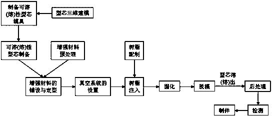
[0030] Including the following steps:

[0031] 1. Three-dimensional modeling of the core: make the core drawing according to the design size of the fuel tank, and then use the three-dimensional modeling software UG, ProE, Solid works, CATIA, etc. Carry out cutting, select 10 representative sections in the fuel tank core model, and reduce the dimensions around the 10 sections by 30mm on each side, and print out the reduced section graphics file to form a drawing.

[0032] 2. Preparation of the core model of the third outer fuel tank: According to the CAD cross-sectional drawing of the core established by three-dimensional modeling, 10 FRP partitions in different positions were made, and all the partitions were fixed in series in sequence and position with triangle irons. Together, form a frame; and pour polyurethane foam material between the partitions, after the foaming is complete, trim it according to the size of the partition, and then use epoxy resin LT-5078, biaxial E-BX8...

Embodiment 2

[0049] The difference between this embodiment and Embodiment 1 is that the water-soluble core is replaced by a meltable core. details as follows:

[0050] In step 3, the preparation of the fusible core: first, remake the core forming mold according to the core model, the same as in Example 1; after that, select an alloy material with a melting point within 100°C (such as Bi with a melting point of 102.5°C, Sn, Cd ternary alloy, the weight ratio is 54:26:20) as raw material, configure the low melting point mandrel material that can meet the molding requirements, melt the fusible alloy material, and use the fusible core casting mold to cast Shape and sand the surface of the fusible core (step 4).

[0051] In step 13, the fusible core of the third outer fuel tank is melted out: the composite fuel tank part with the fusible core is placed in a hot oven at 105°C until the fusible core is completely melted, and poured out. A third outer fuel tank product made of composite material...


PUM

PropertyMeasurementUnit
Thicknessaaaaaaaaaa
Melting pointaaaaaaaaaa

Abstract

The invention discloses a vacuum assisted resin transfer molding integral-forming technology of a composite material fuel-tank. A novel structural material fuel-tank is provided. Structural weight of a present fuel tank and vehicle noise level can be reduced effectively, and the novel structural material fuel-tank has characteristics of impact damage resistance, corrosion resistance and the like. Meanwhile, forming process cycle of the fuel tank can be greatly shortened, and production efficiency of the fuel tank can be raised. The technology is realized by the following technical scheme: core three-dimensional modeling; core forming-die manufacturing; soluble (fusible) core manufacturing; die preparation; laying and shaping of a reinforcing material; die locking; making of a resin solution; resin injection; resin curing; demoulding; core dissolution (fusing); and composite material product finishing. By the technology, production efficiency is high; demoulding is convenient; and cost is low.

Description

technical field [0001] The present invention relates to a vacuum assisted resin transfer molding (VARTM for short) overall forming process of a composite fuel tank, in particular to the compounding process using a vacuum assisted resin transfer molding process and a soluble (melting) mandrel. The process of integral forming of material components. Background technique [0002] As a storage device for power oil of cars, heavy trucks and special vehicles, fuel tanks are widely used in various types of transportation vehicles and are an important part of transportation vehicles. At present, fuel tanks in the field of cars have been gradually plasticized. The application of plastic fuel tanks has reduced the weight of cars to a certain extent. However, the strength of plastic fuel tanks is relatively low, and they are easily damaged when subjected to external forces, which may easily cause fuel to leak out and even cause fires; heavy-duty The fuel tanks of trucks and special ve...

Claims


Application Information

Patent Timeline
IPC IPC(8): B29C70/44B29C70/48B29C70/30B29C33/38B29C33/52
CPCB29C33/3842B29C33/3892B29C70/48
Inventor 张彦飞刘亚青赵贵哲许国栋刘昭特
Owner ZHONGBEI UNIV
Why Eureka
Try Eureka