Ceramic cylindrical sputtering target and method for producing same

A technology of sputtering target material and manufacturing method, which is applied to manufacturing tools, sputtering coating, ceramic molding machines, etc., can solve the problem of increasing the number of arcs, and achieve the effect of less generation and high density

Active Publication Date: 2014-09-24
MITSUI MINING & SMELTING CO LTD
View PDF7 Cites 18 Cited by
  • Summary
  • Abstract
  • Description
  • Claims
  • Application Information

AI Technical Summary

Problems solved by technology

Therefore, when sputtering is performed using a long cylindrical target obtained by the sputtering method, the number of arcs will increase.

Method used


Image

  • Ceramic cylindrical sputtering target and method for producing same
  • Ceramic cylindrical sputtering target and method for producing same
  • Ceramic cylindrical sputtering target and method for producing same

Examples


Embodiment 1

[0108] The specific surface area measured by the BET method is 10m 2 / g of SnO 2 Powder and specific surface area measured by BET method is 10m 2 / g In 2 o 3 powder to make SnO 2 The amount becomes 1% by mass and is mixed in a tank with zirconia balls in a ball mill to prepare a ceramic raw material powder.

[0109] In this tank, as binder, add the polyvinyl alcohol (polymerization degree: 280, alkalization degree is mol percent 68%) for ceramic raw material powder by mass percent, as dispersant, add mass percent for ceramic raw material powder 0.3% of ammonium polycarboxylate, and as a dispersion medium, 15% by mass of water was added to the ceramic raw material powder and mixed in a ball mill to prepare a slurry. The ratio of the amount of ceramic raw material powder to the total amount of organic additives (the total amount of polyvinyl alcohol and ammonium polycarboxylate) was 0.4% by mass.

[0110] This slurry was supplied to a spray drying apparatus, and spray dryi...

Embodiment 2~20

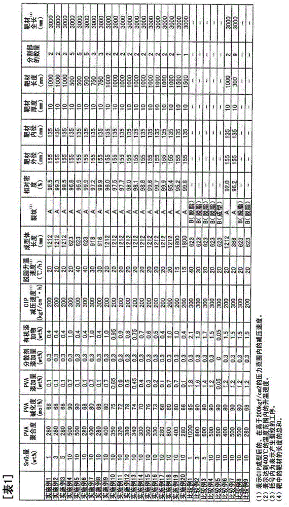
[0117] [Examples 2-20, Comparative Examples 1-9]

[0118] Examples 2-20 and Comparative Examples 1-9 were implemented on the following conditions.

[0119] SnO in the ceramic raw material powder 2 The content of powder, the degree of polymerization of polyvinyl alcohol and the degree of alkalization, the addition amount of polyvinyl alcohol, and the addition amount of ammonium polycarboxylate are set as the conditions shown in Table 1, and the same method as in Example 1 is used except that way to prepare particles.

[0120] The pellets were subjected to CIP molding to produce cylindrical molded bodies having the lengths shown in Table 1. In CIP molding, Examples 2, 3, 9 to 18, and Comparative Example 6 use the same polyurethane rubber mold as in Example 1, while other Examples and Comparative Examples use the same polyurethane rubber mold as in Example 1. The rubber molds have the same core and inner diameter, and are urethane rubber molds having the lengths to obtain mold...

Embodiment 21

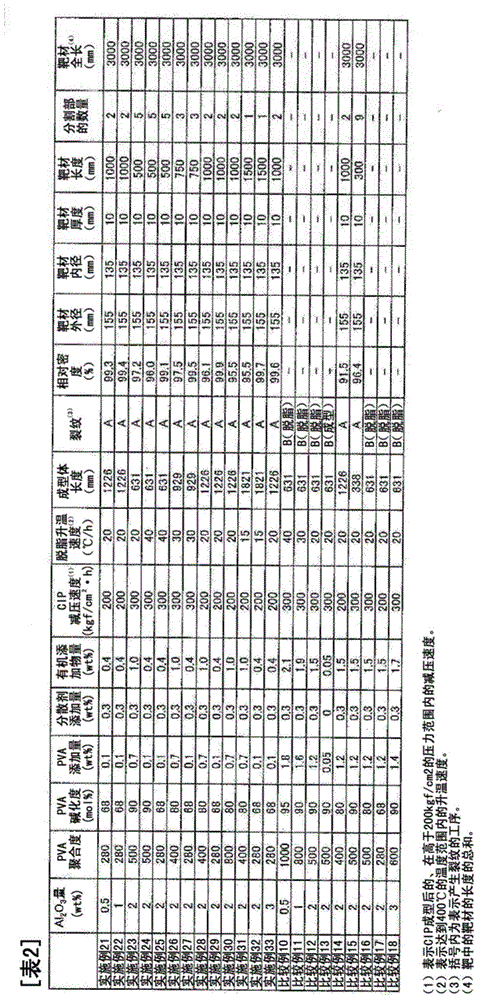
[0127] The specific surface area measured by the BET method is 5m 2 / g Al 2 o 3 Powder and specific surface area measured by BET method is 10m 2 / g ZnO powder to make Al 2 o 3 content of 0.5% by mass, and mixed in a tank with zirconia balls in a ball mill to prepare ceramic raw material powder.

[0128] Except having used this ceramic raw material powder, it carried out similarly to Example 1, and produced the pellet.

[0129]Under the same conditions as in Example 1, a cylindrical core (mandrel) with an inner diameter of 213 mm (thickness of 10 mm) and a length of 1233 mm was used with a top and bottom sealable cap and a cylindrical core (mandrel) with an outer diameter of 167 mm. The pellets were subjected to CIP molding to produce cylindrical moldings having the lengths shown in Table 2.

[0130] This molded body was degreased under the same conditions as in Example 1.

[0131] The degreased molded body was sintered under the same conditions as in Example 1 to produc...


PUM

PropertyMeasurementUnit
lengthaaaaaaaaaa
lengthaaaaaaaaaa
lengthaaaaaaaaaa

Abstract

The present invention provides a ceramic cylindrical sputtering target characterized in being a single article having a length of 500 mm or longer and a relative density of 95% or greater. The ceramic cylindrical sputtering target is a single article having a high density and length of 500 mm or longer and therefore eliminates the need to use a stack of multiple sputtering targets in order to obtain a long target. Consequently, when the ceramic cylindrical sputtering target of the present invention is used in a magnetron rotary cathode sputtering target, and the like, there are no or few partitions in the target as a whole and therefore there is little arcing and particle generation during sputtering.

Description

technical field [0001] The present invention relates to a ceramic cylindrical sputtering target and a manufacturing method thereof, more specifically, to a high-density and long ceramic cylindrical sputtering target and a manufacturing method thereof. Background technique [0002] The magnetron-type rotary cathode sputtering device is a device that has a magnetic field generator inside a cylindrical target, and rotates the target while cooling from the inside of the target to perform sputtering, and the entire surface of the target is covered with acid. Erosion is thus evenly cut. Therefore, the magnetron rotary cathode sputtering device can obtain a very high use efficiency of more than 60% compared to the use efficiency of the flat-plate magnetron sputtering device of 20-30%. Furthermore, since the target is rotated, a large power can be input per unit area compared with the conventional flat-plate magnetron sputtering apparatus, and thus a high film-forming rate can be o...

Claims


Application Information

Patent Timeline
Patent Type & Authority Applications(China)
IPC IPC(8): C04B35/632C04B35/00C23C14/34
CPCC04B35/638C04B2235/6562C23C14/3407C04B2235/5409C04B2235/6567C04B35/453C04B35/634C04B2235/3286C04B2235/3284C04B2235/77C04B2235/3217C04B35/632C04B2235/94C23C14/3414C04B35/457C04B2235/3293C04B35/00C04B35/62695B28B3/003B28B11/243C04B35/01C04B35/622C04B35/63416C04B2235/6022
Inventor 真崎贵则石田新太郎
Owner MITSUI MINING & SMELTING CO LTD
Why Eureka
Try Eureka