

Boiler energy saving and emission reduction system based on flue gas waste heat recovery and reheating technology
A flue gas waste heat, energy-saving and emission-reducing technology, which is applied in indirect carbon dioxide emission reduction, lighting and heating equipment, combustion methods, etc., can solve problems such as rising exhaust gas temperature, intensified corrosion, and increased flue gas volume, and achieves improved The effect of raising the height, reducing the corrosion, and reducing the specific resistance
- Summary
- Abstract
- Description
- Claims
- Application Information
AI Technical Summary
Problems solved by technology
Method used
Image

Examples
Embodiment Construction
[0030] The present invention is described in further detail below in conjunction with accompanying drawing:
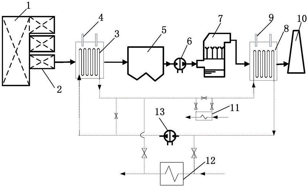
[0031] refer to figure 1 The boiler energy saving and emission reduction system based on flue gas waste heat recovery and reheating technology according to the present invention includes an air preheater 2, a flue gas cooler 3, an electrostatic precipitator 5, a desulfurization tower 7, a flue gas reheater 8 and The chimney 10, the flue gas inlet of the air preheater 2 is connected with the flue gas outlet of the boiler 1, the flue gas outlet of the air preheater 2 is connected with the flue gas inlet of the flue gas cooler 3, and the flue gas cooler 3 The flue gas outlet is connected to the flue gas inlet of the electrostatic precipitator 5, the flue gas outlet of the electrostatic precipitator 5 is connected to the tail flue gas inlet of the desulfurization tower 7, and the desulfurization flue gas outlet of the desulfurization tower 7 is connected to the flue gas re...
PUM
 Abstract
Description
Claims
Application Information