Online projection objective wave aberration detection device and method

A technology of projection objective lens and detection device, which is applied to exposure devices of photoengraving process, testing optical performance, exposure equipment of microlithography, etc. Light source spatial coherence and other issues, to achieve the effect of improving modulation effect, improving wave aberration detection accuracy, and eliminating the influence of phase extraction accuracy

Active Publication Date: 2014-11-26
SHANGHAI INST OF OPTICS & FINE MECHANICS CHINESE ACAD OF SCI
View PDF9 Cites 24 Cited by
  • Summary
  • Abstract
  • Description
  • Claims
  • Application Information

AI Technical Summary

Problems solved by technology

However, the problem with this device is that the light source is partially coherent light, which directly affects the modulation effect of the spatial coherence of the light field and thus affects the measurement accuracy.
U.S. Patent No. 7,333,216 discloses a wave aberration detection device that adopts a multimode fiber array to reduce the spatial coherence of the light source (refer to prior art [2], U.Wegmann, H.Haidner, M.Schriever.Apparatus for wavefront detection, United States patent US7333216B2,2008.), but the problem with this device is that there is no effective alignment and parallel adjustment function between the object plane grating and the image plane grating, and it is easy to introduce system errors
Matthieu Visser et al. proposed an extended light source interferometer for EUV lithography objective lens wave aberration detection (refer to prior art [3], Matthieu Visser, Martign K.Dekker, Petra Hegeman, et al., "Extended source interferometry for at-wavelength test of EUV-optics”, Emerging Lithographic Technologies Iii, Pts 1 and 2, 1999.3676: p.253-263), but the problem is that the interference between the higher order diffraction items and the 0th order has not been eliminated

Method used


Image

  • Online projection objective wave aberration detection device and method
  • Online projection objective wave aberration detection device and method
  • Online projection objective wave aberration detection device and method

Examples


Embodiment

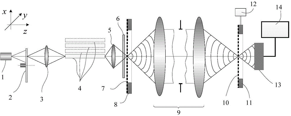
[0064] In the DUV exposure optical system, the light source 1 is generally ArF and KrF excimer lasers, that is, the wavelengths of the output light are 193nm and 248nm respectively. With an ArF excimer laser with a wavelength of 193nm as the light source 1, the numerical aperture of the measured optical system 9 is 0.75, the imaging magnification is 4×, the shear rate is set to 1 / 20, and the period P of the image plane grating 801 is selected. i is 2.6μm, and the object plane grating period is P o The period of the fifth grating and the sixth grating of the image plane grating alignment mark are 25 μm and 26 μm respectively; the periods of the third grating and the fourth grating of the object plane grating mark are 104 μm and 100 μm respectively.

[0065] The object-plane grating displacement stage 8 is a displacement stage that moves the first grating 701 and the second grating 702 into the object-side optical path of the measured optical system 9 respectively;

[0066] The...


PUM


Abstract

The invention relates to an online projection objective wave aberration detection device and method. The detection device comprises a light source, a rotary scatterer, a first focusing lens, an optical fiber array, a second focusing lens, a scattering optical element, an object plane optical grating, an image plane optical grating, a two-dimensional photoelectric sensor, a phase-shift control module and a computer, wherein the rotary scatterer is composed of a support, an electric motor and a circular diffusion scattering optical element, and is combined with the multimode optical fiber array for converting a coherent light or partially coherent light source into incoherent light; ten interference fringe patterns with phase shifting amounts of 0, pi/6, pi/3, pi/2, 2pi/3, 5pi/6, pi, 5pi/3, 3pi/2 and 11pi/6 respectively are acquired to calculate a phase position and the influence of multilevel diffraction light interference of the optical grating on the phase position extraction precision is eliminated. The device and the method can improve the modulation effect of the object plane optical grating on the optical field spatial coherence so as to achieve a high-precision alignment effect, reduce the system error of phase position extraction in wave aberration detection and improve the wave aberration detection precision of an optical system.

Description

technical field [0001] The invention relates to a wave aberration detection device of an optical system, in particular to an online wave aberration detection device and method of a projection objective lens of a lithography machine illuminated by an expanded light source. Background technique [0002] Photolithography technology is one of the core technologies in the manufacture of very large-scale integrated circuits. The pattern on the mask is transferred to the photoresist coated on the surface of the silicon wafer by exposure method, and then the pattern is transferred by developing, etching and other processes. transferred to silicon wafers. The projection objective lens is the core component of the imaging system of the lithography machine. The wave aberration of the projection objective lens is the main factor leading to the deterioration of the lithography imaging quality, and ultimately leads to the decrease of the imaging contrast of the lithography machine, the na...

Claims


Application Information

Patent Timeline
Patent Type & Authority Applications(China)
IPC IPC(8): G03F7/20G01M11/02
Inventor 吴飞斌唐锋王向朝李杰李永
Owner SHANGHAI INST OF OPTICS & FINE MECHANICS CHINESE ACAD OF SCI
Why Eureka
Try Eureka