A horizontal high-pressure gas quenching-tempering-nitridation vacuum multipurpose furnace

A high-pressure gas, quenching and tempering technology, applied in the direction of quenching device, furnace, furnace type, etc., can solve the problems of unsatisfactory ventilation structure, unfavorable diffusion process, affecting nitriding speed and quality, etc., and achieves favorable adsorption and interface reaction. , The process control is simple, the effect of preventing oxidation of parts

Active Publication Date: 2014-12-10
北京华翔电炉技术有限责任公司
View PDF5 Cites 12 Cited by
  • Summary
  • Abstract
  • Description
  • Claims
  • Application Information

AI Technical Summary

Problems solved by technology

[0002] At present, the external heating gas nitriding furnace used in China has the following disadvantages: (1) The heat energy consumption is large: the parts that need to be nitrided are placed in the nitriding tank made of heat-resistant steel, heated in the pit furnace, and the nitriding tank As light as one or two hundred kilograms, as heavy as five or six hundred kilograms, or even heavier, it consumes a lot of heat energy
In order to increase the cooling speed, some put the furnace tank out for air cooling, and some add an air cooling system on the furnace body, but the cooling is still very slow.
(3) Low pressure of nitriding atmosphere: The pressure of nitriding atmosphere in the tank is low, usually only tens of millimeters of oil column, the atmosphere pressure is not high, which greatly affects the speed and quality of nitriding
(4) The air intake structure is unreasonable: most furnaces insert a vent pipe from the top of the nitriding tank to the bottom of the tank, and the ammonia gas flows from the bottom of the tank to the inside of the tank, and is discharged from the gas outlet
Therefore, this vent structure is not ideal
(5) Not conducive to diffusion: In order to eliminate the brittle phase layer (white layer) on the surface of the nitriding layer, the diffusion process under the condition of high decomposition rate is adopted. However, at the nitriding temperature, it is difficult to achieve no active nitrogen atoms in the atmosphere The presence, therefore, is detrimental to the diffusion process

Method used


Image

  • A horizontal high-pressure gas quenching-tempering-nitridation vacuum multipurpose furnace

Examples


Embodiment Construction

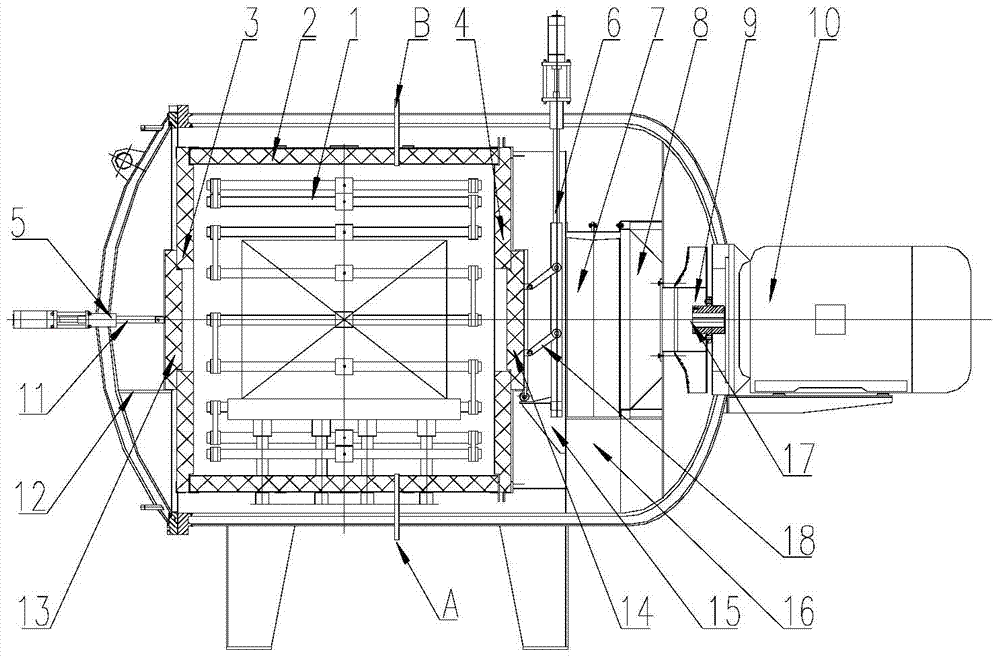
[0018] The present invention will be described in detail below in conjunction with the accompanying drawings.

[0019] The invention includes a vacuum furnace main body, a heating chamber, an air-cooling system, a vacuum unit, a gas supply system, and an electrical control system. Aiming at the disadvantages of the traditional nitriding furnace using a nitriding tank structure, such as slow heating and cooling speeds, the nitrogen chemical The parts are placed directly in the heating chamber.

[0020] The heating chamber includes a heating element (1), a cylinder body (2), a front cover (3), and a rear cover (4). The heating element (1) is formed into a cylindrical shape by 18 graphite rods through a connecting plate, and the wiring The form is triangular, and the heat shield of the cylinder body (2) includes composite hard felt, graphite soft felt, ceramic fiber felt and stainless steel guard plate. The front cover (3) and the rear cover (4) are composed of heat insulation la...


PUM


Abstract

The invention discloses a horizontal high-pressure gas quenching-tempering-nitridation vacuum multipurpose furnace and relates to the field of metal vacuum thermal treatment. The furnace comprises a vacuum furnace main body, a heating chamber, a wind cooling system, a vacuum unit, a gas supplying system and an electric control system. The heating chamber comprises heating elements, a cylinder, a front cover and a back cover. The front cover and the back cover are provided with wind guiding holes. An air cylinder drives movable doors to open and close the wind guiding holes so as to guarantee circular flowing of cooling gas during tempering and gas quenching and to guarantee a closed structure of the heating chamber during nitridation. The furnace overcomes the disadvantages caused by adoption of metal nitridation tanks adopted by nitridation furnaces at present, namely slow heating and cooling speeds, low atmosphere pressure, and the like. The furnace is provided with using conditions for high-pressure high-flow-rate quenching and tempering, is simple in structure and practical, and truly achieves the using requirements on vacuum multipurpose furnaces.

Description

technical field [0001] The invention relates to the field of vacuum furnaces, in particular to a horizontal high-pressure gas quenching, tempering and nitriding vacuum furnace. Background technique [0002] At present, the external heating gas nitriding furnace used in China has the following disadvantages: (1) The heat energy consumption is large: the parts that need to be nitrided are placed in the nitriding tank made of heat-resistant steel, heated in the pit furnace, and the nitriding tank As light as one or two hundred kilograms, as heavy as five or six hundred kilograms, or even heavier, the heat energy consumption is very large. (2) Slow cooling: due to indirect heating, the temperature of nitriding parts is slow to rise, and the temperature is also slow. In order to increase the cooling speed, some put the furnace tank out for air cooling, and some add an air cooling system on the furnace body, but the cooling is still very slow. (3) Low pressure of nitriding atmos...

Claims


Application Information

Patent Timeline
Patent Type & Authority Applications(China)
IPC IPC(8): C23C8/20C21D1/62C21D1/773C21D9/00
Inventor 杜利民刘文瑛李世萍刘晓伟
Owner 北京华翔电炉技术有限责任公司
Why Eureka
Try Eureka