Equalizing charge circuit and battery pack

A technology of balanced charging and battery packs, applied in battery circuit devices, circuit devices, current collectors, etc., can solve the problems of global impact, high system requirements, and large energy loss, achieving small global impact, low system requirements, and energy loss. small effect

Active Publication Date: 2014-12-10
MORNSUN GUANGZHOU SCI & TECH
View PDF9 Cites 25 Cited by
  • Summary
  • Abstract
  • Description
  • Claims
  • Application Information

AI Technical Summary

Problems solved by technology

Its disadvantages are: the control is complicated. If you want to temporarily change the number of series cells of the battery pack, you must use three cells as a group. The degaussing of the power supply is not mentioned
[0009] The Chinese application number 201010034137.0 of the Institute of Electrical Engineering, Chinese Academy of Sciences authorized the invention "A Balanced Equipment for Series Battery Packs", which shows: an improved version of 200810063915.1, which is also a working group of three single batteries. During charging or discharging, the extra The disadvantage of releasing energy to this working group is that the control is complicated. If you want to temporarily change the number of series cells of the battery pack, you must use three cells as a group. Only the basic topology is involved, and the demagnetization of the switching power supply is not mentioned
[0010] 3. The 201110043546.1 application of AVIC Lithium Battery (Luoyang) Co., Ltd. "A Charge and Discharge Equalization Circuit for Multi-cell Series Power Lithium Battery Pack" shows that: the voltage of this level of battery is high, and it is transmitted to another battery step by step, and the number of stages is more , large energy loss
At present, the efficiency of the switching efficiency is 90%, which is relatively high. After 6 stages of transmission, the e

Method used


Image

  • Equalizing charge circuit and battery pack
  • Equalizing charge circuit and battery pack
  • Equalizing charge circuit and battery pack

Examples


no. 1 example

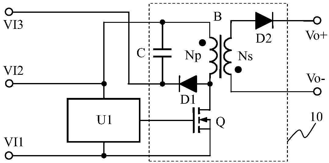
[0039] see image 3 , is a balanced charging circuit, used in parallel with a single battery in the series battery pack, including the first input terminal VI1, the second input terminal VI2, the third input terminal VI3, the output positive terminal Vo+, and the output negative terminal Vo -, the detection circuit U1 and the flyback DC-DC converter 10 controlled by the detection circuit U1, the flyback DC-DC converter 10 includes an N-MOS transistor Q (N-MOS is an N-channel metal oxide semiconductor field effect tube), transformer B, first diode D1, second diode D2, capacitor C; the detection circuit U1 is connected in parallel between the first input terminal VI1 and the second input terminal VI2, and the output terminal of the detection circuit It is connected to the gate of the N-MOS transistor Q, the source of the N-MOS transistor Q is connected to the first input terminal VI1, and the drain of the N-MOS transistor Q is connected to the primary winding N of the transforme...

no. 2 example

[0054] Therefore, the present invention also provides a battery pack using a plurality of equalizing charging circuits, each single battery in the battery pack uses a corresponding equalizing charging circuit, and the output positive terminals of all equalizing charging circuits are connected together and connected to the battery On the positive pole of the battery pack, the output negative terminals are connected together and connected to the negative pole of the battery pack. Among them, the single battery closest to the positive pole of the battery pack is called the first single battery, and the serial numbers of the other single batteries are deduced by analogy. Features are:

[0055] The first equalizing charging circuit (hereinafter referred to as the first circuit) applied to both ends of the first single battery in the battery pack, the first input terminal of the first circuit is connected to the negative pole of the first single battery, the second of the first circu...

no. 3 example

[0061] Equalizing charging circuit using P-MOS tube, see Figure 4 , Figure 5 shows and Figure 4 The schematic diagram of the connection relationship is exactly the same, in order to facilitate the understanding of the equalization charging circuit using the P-MOS tube applied to the first single battery.

[0062] The connection relationship is that a balanced charging circuit using P-MOS transistors includes a first input terminal VI1, a second input terminal VI2, a third input terminal VI3, an output positive terminal Vo+, an output negative terminal Vo-, and a detection circuit U1 And the flyback DC-DC converter 10 controlled by the detection circuit U1, the output positive terminal Vo+ is connected to the positive pole of the battery pack, and the output negative terminal Vo- is connected to the negative pole of the battery pack; the flyback DC-DC The converter 10 includes a P-MOS transistor Q, a transformer B, a first diode D1, a second diode D2, and a capacitor C; th...


PUM


Abstract

An equalizing charge circuit comprises a first input end, a second input end, a third input end, an output plus end, an output minus end, a detection circuit U1 and a flyback DC-DC converter 10. The junction of a drain of an N-MOS (N-channel metal oxide semiconductor) transistor Q and a primary winding NP of a transformer B is further connected with an anode of a diode D1, a cathode of the diode D1 is connected with the third input end, and a capacitor C is parallelly connected between the second input end and the third input end. The output plus end is connected on the anode of the batter pack, and the output minus end is connected on the cathode of the battery pack. When the detection circuit detects that voltage of a battery cell is larger than a set value, the converter 10 starts working, charge current to the battery cell is extracted and returned to charge the chatter pack, energy generated by leakage inductance of the flyback converter can be used for charging a previous battery cell, and accordingly equalizing charge of the battery pack is realized; when the detection circuit U1 composed of a single chip microcomputer is utilized, an infrared receiving head is added to synchronously adjust a set value, and equalizing discharge can be realized. The flyback circuit is high in reliability, simple in composition, low in cost, high in efficiency and easy to maintain.

Description

technical field [0001] The invention relates to a charging device for a battery pack or a supercapacitor pack, in particular to a balanced charging circuit for each monomer in the battery pack or the supercapacitor pack. Background technique [0002] At present, in systems where batteries are used as energy storage units, the capacity of individual batteries is relatively low, which cannot meet the requirements of large-capacity systems. Therefore, it is necessary to connect individual batteries in series to form a battery pack; parallel connection can increase capacity, but its terminal voltage is still very high. Low, it is still regarded as a "single" battery. In this case, it is used directly. Due to the considerable loss of the switching device and the voltage drop of the diode, in high-power applications, it is still necessary to connect the single cells in series to form a battery pack, such as figure 1 As shown, in order to improve the power supply voltage and storag...

Claims


Application Information

Patent Timeline
IPC IPC(8): H02J7/00
Inventor 王保均
Owner MORNSUN GUANGZHOU SCI & TECH
Why Eureka
Try Eureka