High-efficiency back contact solar cell back sheet without main grids, high-efficiency back contact solar cell assembly without main grids and manufacturing technology

A solar cell and high-efficiency technology, applied in the field of solar cells, can solve the problems of complex manufacturing process of conductive backplane, slow etching speed, and increased manufacturing cost, so as to reduce electron collection distance, reduce series resistance, and reduce manufacturing cost Effect

Active Publication Date: 2015-01-07
JOLYWOOD SUZHOU SUNWATT
View PDF5 Cites 7 Cited by
  • Summary
  • Abstract
  • Description
  • Claims
  • Application Information

AI Technical Summary

Problems solved by technology

This process has the following defects: 1. The composite conductive backplane used is a composite conductive metal foil in the backplane, usually copper foil, and the copper foil needs to be laser etched or chemically etched
Since laser etching is still operable for simple patterns, the etching speed is slow and the production efficiency is low for complex patterns, while chemical etching requires pre-prepared complex-shaped and corrosion-resistant masks, environmental pollution and corrosive liquids on polymers. Substrate corrosion problems
Therefore, the manufacturing process of the conductive backplane manufactured in this way is complicated and the cost is extremely high.
2. It is necessary to punch the packaging material of the back layer of the solar cell so that the conductive adhesive can penetrate the packaging material. Since the packaging material is usually a viscoelastic body, it is extremely difficult to accurately punch holes
3. Accurate dispensing equipment is required to coat the conductive glue on the corresponding position of the back plate. It can also be operated for batteries with fewer back contacts such as MWT, and for back contact batteries with small and large number of back contacts such as IBC. Simply not possible with dispensing equipment
However, a large number of conductive parts are required to effectively collect current, thus resulting in increased manufacturing costs and complicated process steps
[0009] Patent EP2709162A1 discloses a solar cell, which is

Method used


Image

  • High-efficiency back contact solar cell back sheet without main grids, high-efficiency back contact solar cell assembly without main grids and manufacturing technology
  • High-efficiency back contact solar cell back sheet without main grids, high-efficiency back contact solar cell assembly without main grids and manufacturing technology
  • High-efficiency back contact solar cell back sheet without main grids, high-efficiency back contact solar cell assembly without main grids and manufacturing technology

Examples


Embodiment 1

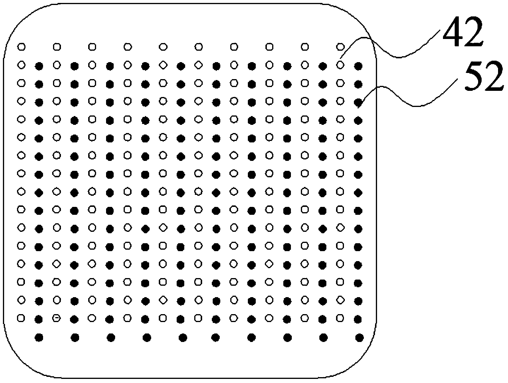
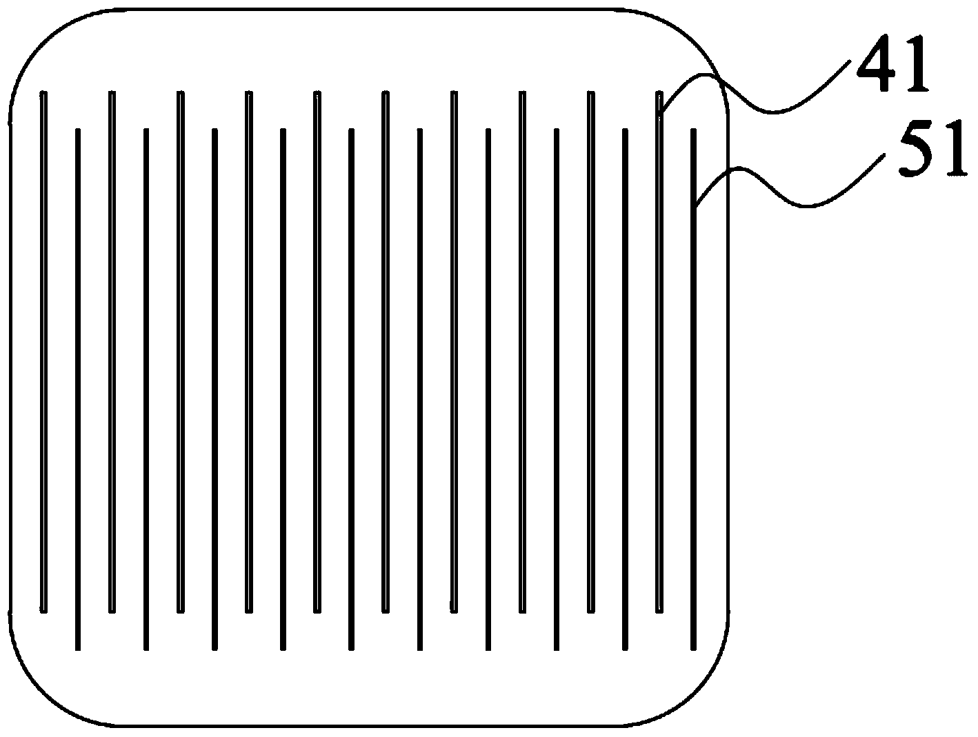
[0080] see figure 1 , image 3 , Figure 4 , Image 6 , a busbar-free, high-efficiency back-contact solar cell backsheet provided in this embodiment, the back-contact solar cell backsheet is an electrical connection layer and a base layer in sequence from top to bottom, and the connection between the electrical connection layer and the base layer connected by an adhesive; the electrical connection layer may include more than two groups of finger electrodes, and each group of finger electrodes is alternately arranged in an interdigitated shape, and the finger electrodes are electrically connected to the P electrode or N electrode. The adjacently arranged interdigitated electrodes are electrically connected to electrodes of different doped layers.

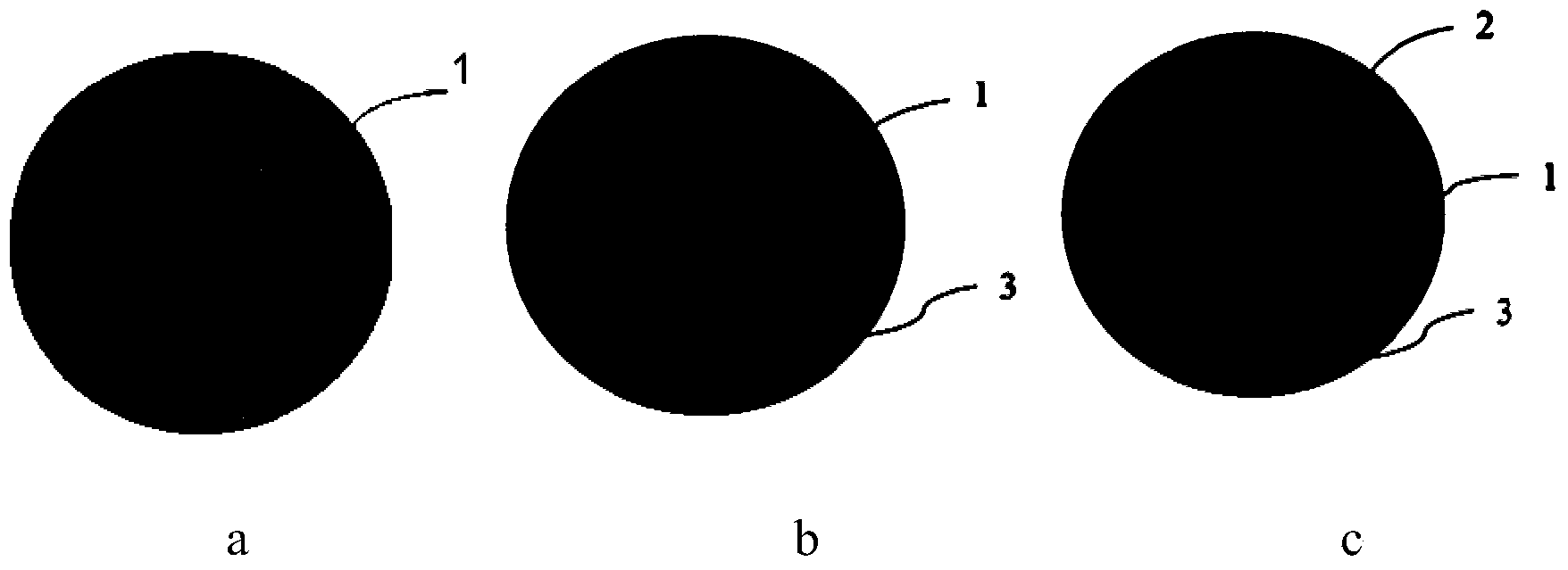
[0081] see Figure 4 , the bus bar electrode is arranged at the base of the finger electrode, and the surface of the bus bar electrode has a concave-convex shape, which can increase the ohmic contact area of ​​the bus bar electro...

Embodiment 2

[0099] see figure 2 , image 3 , Figure 4 , Figure 5 , a busbar-free, high-efficiency back-contact solar cell backsheet provided in this embodiment, the back-contact solar cell backsheet is an electrical connection layer and a base layer in sequence from top to bottom, and the connection between the electrical connection layer and the base layer connected by an adhesive; the electrical connection layer may include more than two groups of finger electrodes, and each group of finger electrodes is alternately arranged in an interdigitated shape, and the finger electrodes are electrically connected to the P electrode or N electrode. The adjacently arranged interdigitated electrodes are electrically connected to electrodes of different doped layers.

[0100] see Figure 4 , the bus bar electrode is arranged at the base of the finger electrode, and the surface of the bus bar electrode has a concave-convex shape, which can increase the ohmic contact area of ​​the bus bar electro...

Embodiment 3

[0118] see figure 1 , image 3 , Figure 4 , Figure 7 , a busbar-free, high-efficiency back-contact solar cell backsheet provided in this embodiment, the back-contact solar cell backsheet is an electrical connection layer and a base layer in sequence from top to bottom, and the connection between the electrical connection layer and the base layer connected by an adhesive; the electrical connection layer may include more than two groups of finger electrodes, and each group of finger electrodes is alternately arranged in an interdigitated shape, and the finger electrodes are electrically connected to the P electrode or N electrode. The adjacently arranged interdigitated electrodes are electrically connected to electrodes of different doped layers.

[0119] see Figure 4 , the bus bar electrode is arranged at the base of the finger electrode, and the surface of the bus bar electrode has a concave-convex shape, which can increase the ohmic contact area of ​​the bus bar electr...


PUM

PropertyMeasurementUnit
Diameteraaaaaaaaaa
Thicknessaaaaaaaaaa
Particle sizeaaaaaaaaaa

Abstract

The invention relates to the field of solar cells, in particular to a high-efficiency back contact solar cell back sheet without main grids, a high-efficiency back contact solar cell assembly without main grids and a manufacturing technology of the high-efficiency back contact solar cell assembly. The back contact solar cell back sheet is characterized by sequentially comprising an electric connection layer and a basic layer from top to bottom, the electric connection layer and the basic layer are connected through adhesive, and the electric connection layer comprises two or more finger-shaped electrodes, all the finger-shaped electrodes are alternatively arrayed in an interdigital shape, and the electric connection layer is used for being connected with a back contact cell piece. The back contact solar cell back sheet has the advantages of being high in efficiency and resistant to subfissure, shading losses of grid line electrodes on the front face are eliminated, and therefore the cell efficiency is improved; the cell can be sheeted, and therefore the cost is lowered; practicability is higher, and the back contact solar cell back sheet is generally suitable for an MWT structure, an EWT structure, an IBC structure and other structures.

Description

technical field [0001] The invention relates to the field of solar cells, in particular to a busbar-free, high-efficiency back-contact solar cell backplane, components and a preparation process thereof. Background technique [0002] Energy is the material basis of human activities. With the continuous development and progress of human society, the demand for energy is increasing day by day. Traditional fossil energy is non-renewable energy and it is difficult to continue to meet the needs of social development. Therefore, research and utilization of new energy and renewable sources have become increasingly popular in countries around the world in recent years. Among them, solar power generation technology has the advantages of directly converting sunlight into electricity, simple use, environmental protection and pollution-free, high energy utilization rate, etc., and has received widespread attention. Solar power generation uses large-area P-N junction diodes to generate p...

Claims


Application Information

Patent Timeline
IPC IPC(8): H01L31/18H01L31/0465H01L31/0224H01L31/049
CPCH01L31/022441H01L31/0516H01L31/18Y02E10/50Y02P70/50
Inventor 林建伟夏文进孙玉海张育政
Owner JOLYWOOD SUZHOU SUNWATT
Why Eureka
Try Eureka