Method for directly molding high-entropy alloy turbine engine hot end component through laser metal
A technology for turbine engine and hot-end components, which is applied in the field of laser metal direct forming of high-entropy alloy turbine engine hot-end components, can solve the problems of difficulty in obtaining high-entropy alloys, difficult processing and manufacturing, and achieves reducing manufacturing costs and meeting application requirements. , the effect of improving efficiency
- Summary
- Abstract
- Description
- Claims
- Application Information
AI Technical Summary
Problems solved by technology
Method used
Image

Examples
Embodiment 1
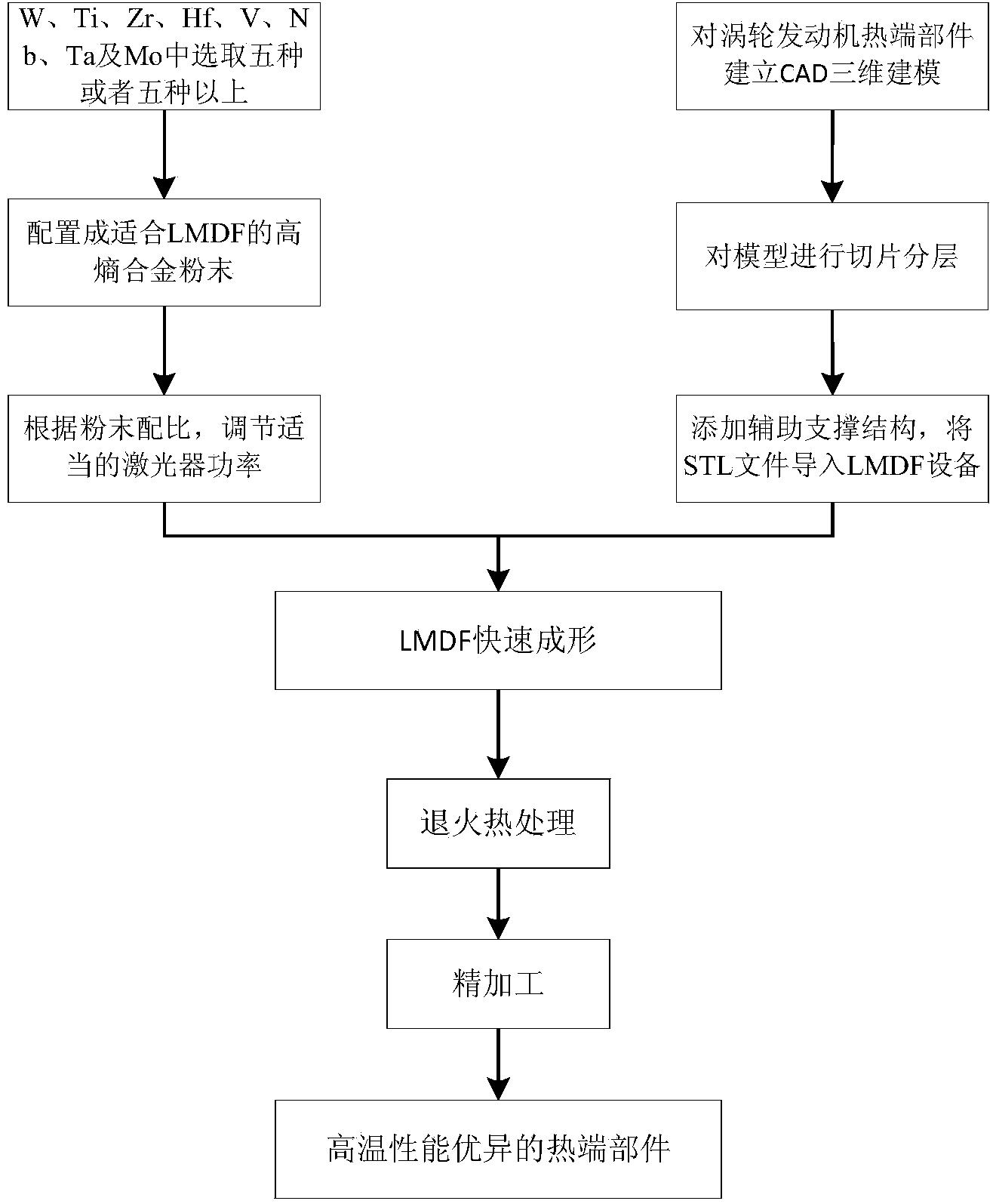
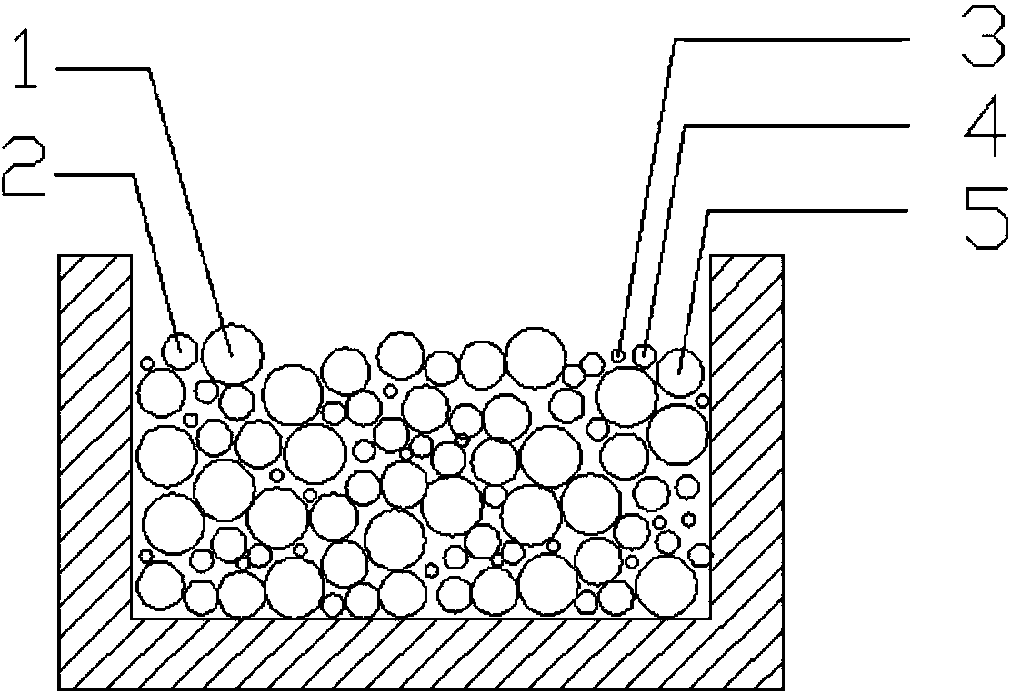
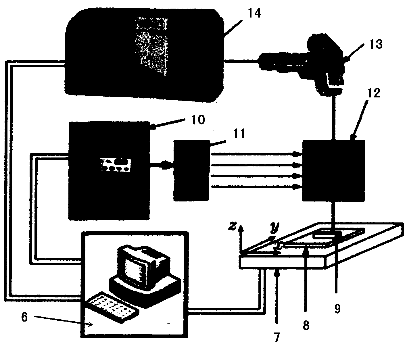
[0053] Five kinds of metals, W, Ti, Zr, V, and Ta, were selected and configured into high-entropy alloy powder according to the equiatomic ratio, and placed in the synchronous powder feeding equipment of LMDF rapid prototyping equipment. UG software is used to establish a 3D CAD model of the hollow turbine blade and sliced and layered, then imported into Magics software to add auxiliary support structures, and the obtained stl format file is then imported into an industrial computer. According to the vapor pressure of these five different elements, the laser power is selected as 200W. At the same time, because the hollow turbine blade has tiny air film holes and exhaust edge structure, and the surface quality and forming accuracy of the formed part are high, it is necessary to use a small The focal length of the lens (100mm) to obtain a fine focus spot size (30μm). The mixed scanning path of contour + grating + partition is adopted, the scanning speed is set to 100 mm / s, and...
Embodiment 2
[0055] Five kinds of metals, W, Ti, Zr, V, and Ta, were selected and configured into high-entropy alloy powder according to the equiatomic ratio, and placed in the synchronous powder feeding equipment of LMDF rapid prototyping equipment. UG software is used to establish a three-dimensional CAD model of the turbine disk, slice and layer it, import it into Magics software to add auxiliary support structures, and then import the obtained stl format file into an industrial computer. According to the vapor pressure of these five different elements, the laser power is selected as 200W. At the same time, due to the fine structure inside the turbine disk and the high requirements for the surface quality and forming accuracy of the formed parts, a lens with a small focal length (100mm) is required to obtain fine Focused spot size (50μm). The mixed scanning path of contour + grating + partition is adopted, the scanning speed is set to 100 mm / s, and the scanning layer thickness Δh is 50 ...
PUM
| Property | Measurement | Unit |
|---|---|---|
| Particle size | aaaaa | aaaaa |
Abstract
Description
Claims
Application Information