A fiber optic time domain reflectometer
A technology of time domain reflectometer and optical fiber, which is applied in the direction of electromagnetic wave transmission system, electrical components, transmission system, etc., can solve the problems of small dynamic range, large dark current and thermal noise, and achieve the goal of increasing dynamic range and improving resolution Effect
- Summary
- Abstract
- Description
- Claims
- Application Information
AI Technical Summary
Problems solved by technology
Method used
Image
Examples
Embodiment 1
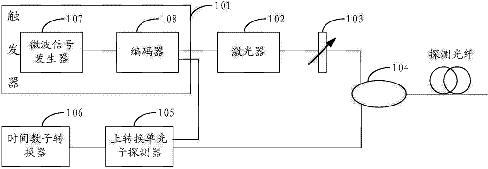
[0056] figure 1 It is a structural schematic diagram of Embodiment 1 of an optical fiber time domain reflectometer according to the present invention, and the device includes:
[0057] Trigger 101 , laser 102 , attenuator 103 , circulator 104 , up-conversion single-photon detector 105 and time-to-digital converter 106 .
[0058] The trigger 101 is used to output an electric pulse signal with a preset frequency.
[0059] Optionally, the trigger 101 includes: a microwave signal generator 107 and an encoder 108,
[0060] The microwave signal generator 107 is used to output an initial pulse signal;
[0061]The encoder 108 is used to encode the initial pulse signal, and output an electric pulse signal with a preset frequency.
[0062] It should be noted here that the trigger 101 can also be composed of other devices capable of outputting electrical pulse signals with a preset frequency, and details will not be repeated here.
[0063] Optionally, the model of the microwave signa...
Embodiment 2
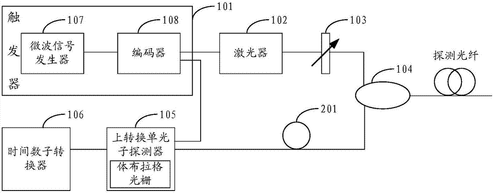
[0104] figure 2 It is a schematic structural diagram of Embodiment 2 of an optical fiber time domain reflectometer according to the present invention. Compared with Embodiment 1, the device further includes a polarization controller, and the device includes:
[0105] Trigger 101 , laser 102 , attenuator 103 , circulator 104 , up-converting single photon detector 105 , time-to-digital converter 106 and polarization controller 201 .
[0106] Wherein, the optical signal is transmitted between the laser 102 , the attenuator 103 , the circulator 104 and the up-conversion single-photon detector 106 through a single-mode optical fiber.
[0107] The pulse signal light passes between the laser 102, the attenuator 103, the circulator 104 and the detection fiber, and the backscattered light passes through the single-mode fiber optic transmission.
[0108]The electrical pulse signal output by the trigger 101 triggers the laser 102 to generate the pulse signal light of the same frequenc...
PUM
 Abstract
Description
Claims
Application Information
 - R&D
- Intellectual Property
- Life Sciences
- Materials
- Tech Scout
- Unparalleled Data Quality
- Higher Quality Content
- 60% Fewer Hallucinations
Browse by: Latest US Patents, China's latest patents, Technical Efficacy Thesaurus, Application Domain, Technology Topic, Popular Technical Reports.
© 2025 PatSnap. All rights reserved.Legal|Privacy policy|Modern Slavery Act Transparency Statement|Sitemap|About US| Contact US: help@patsnap.com


