Anodic oxidation method of spare part containing blind hole

An anodizing and blind hole technology, applied in anodizing, electrolytic coating, surface reaction electrolytic coating, etc., can solve the problems of uneven current density distribution, prolonged oxidation time, solution diffusion limitation, etc., to solve the potential and current density Uneven distribution, reducing the risk of short circuits, improving the effect of processing efficiency

Active Publication Date: 2015-04-08
GUANGZHOU INST OF ADVANCED TECH CHINESE ACAD OF SCI
View PDF3 Cites 9 Cited by
  • Summary
  • Abstract
  • Description
  • Claims
  • Application Information

AI Technical Summary

Problems solved by technology

[0003] In practical applications, some parts of pure titanium, titanium alloy, pure aluminum or aluminum alloy need to be anodized, and when these parts have small deep hole design, many difficulties will be encountered in anodizing, the most important of which is Two problems: one is the uneven distribution of potential or current density in the hole; the other is that the diffusion of the solution in the hole is limited, and the solution exchange and heat dissipation are difficult
[0005] However, the above methods have unsatisfactory anodic oxidation effects in blind holes, and are difficult to apply to small deep holes: adjusting the clamping direction of the workpiece cannot fundamentally solve the uneven distribution of voltage and current density on the inner wall and bottom of the blind hole of the part and the difficulty of solution exchange. and other problems; increasing the oxidation voltage and prolonging the oxidation time may cause over-burning of other surfaces except the blind hole, unqualified size, and waste of energy; increasing the auxiliary cathode or other auxiliary solution circulation device, the device needs to be placed in the blind hole Among them, in order to keep a certain distance between the device and the wall and bottom of the blind hole to avoid short circuit or affect the distribution of power lines, the blind hole must have a certain width, and this requirement is obviously not suitable for the small deep hole design on the part

Method used


Image

  • Anodic oxidation method of spare part containing blind hole
  • Anodic oxidation method of spare part containing blind hole

Examples


Embodiment

[0040] In this embodiment, an anodic oxidation method for parts containing blind holes includes the following steps: effective depth area testing, sand blasting, surface pretreatment, anodic oxidation and subsequent procedures, wherein the material of the parts is pure titanium TA1, on which The blind hole is a small deep hole with a size of Φ2mm×10mm.

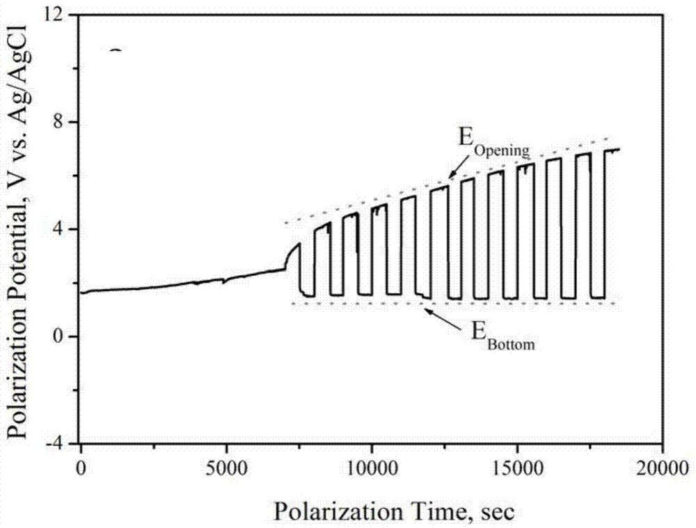
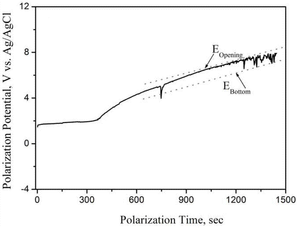
[0041](1) Effective depth area test

[0042] A three-electrode system is adopted, the part is used as the working electrode, phenolic resin is used to cover the part except the small deep hole, only the inner wall of the small deep hole is kept in contact with the electrolyte, and the 5.0mm×5.0mm platinum electrode is used as the auxiliary electrode. The microelectrode Ag / AgCl is the reference electrode, and the working electrode and the auxiliary electrode are facing each other with a distance of about 9 cm.

[0043] The potentiostat is set to the constant current mode (it can also be set to the constant potential mode accor...


PUM

PropertyMeasurementUnit
diameteraaaaaaaaaa

Abstract

The invention discloses an anodic oxidation method of a spare part containing a blind hole. The method comprises the following steps: effective depth region test, sand blasting, surface pretreatment, anodic oxidation and subsequent procedures, wherein the effective depth region test comprises the following processes: providing a reference electrode in the blind hole, and testing potential or current density values of different depth positions in the blind hole, so as to obtain an effective depth region; the sand blasting comprises sand blasting on the effective depth region; surface pretreatment comprises the following processes: carrying out degreasing, alkaline etching and pickling on the spare part after the sand blasting step; anodic oxidation comprises carrying out anodic oxidation according to the anodic oxidation process; and the subsequent procedures are carried out after the anodic oxidation step. According to the method, potential or current density distribution at different depth positions in the blind hole can be effectively smoothed; and the uniformity of the thickness of an anodic oxidation film in the blind hole is improved.

Description

technical field [0001] The invention relates to the field of anodic oxidation, in particular to an anodic oxidation method for parts containing blind holes. Background technique [0002] In the field of mechanical manufacturing, blind holes with a diameter of 0.3 mm to 3 mm are generally called small holes, and blind holes with a hole depth exceeding 5 times the hole diameter are called deep holes, and blind holes that meet these two conditions are called small holes. Diameter deep hole, referred to as small deep hole. Small deep holes are widely used in internal combustion engine oil pump nozzles, various valves, automobiles, electronics, micro-machines, aviation, aerospace and military fields. [0003] In practical applications, some parts of pure titanium, titanium alloy, pure aluminum or aluminum alloy need to be anodized, and when these parts have small deep hole design, many difficulties will be encountered in anodizing, the most important of which is Two problems: o...

Claims


Application Information

Patent Timeline
Patent Type & Authority Applications(China)
IPC IPC(8): C25D11/02C25D7/00
CPCC25D11/022
Inventor 孙学通陈贤帅张春雨欧阳江林
Owner GUANGZHOU INST OF ADVANCED TECH CHINESE ACAD OF SCI
Why Eureka
Try Eureka