A metal component submerged arc surfacing welding forming method
A metal component and submerged arc surfacing technology, which is applied in arc welding equipment, metal processing equipment, welding equipment, etc., to achieve uniform structure, no macro segregation, and outstanding performance in corrosion resistance
- Summary
- Abstract
- Description
- Claims
- Application Information
AI Technical Summary
Problems solved by technology
Method used
Image

Examples
Embodiment 1
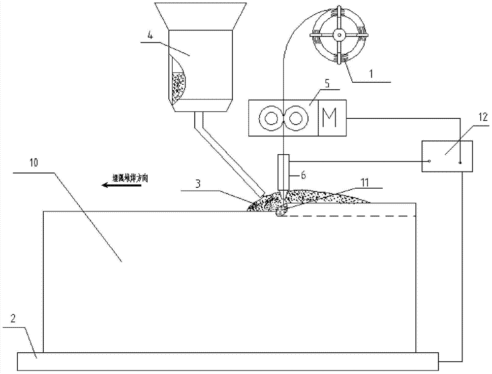
[0027] Horizontal production of flanges. This example describes the process of making flanges by submerged arc surfacing welding. The material is 40Cr and the base material is Q235. The equipment used includes:
[0028] (1) Rotary support table; (2) Power supply; (3) Welding torch; (4) Automatic wire feeding device; (5) Automatic flux delivery and recovery device; (6) Heating device; (7) Cooling device; (8) Substrate; (9) central control device (computer).
[0029] figure 2 It is a schematic explanatory diagram for showing the submerged arc additive manufacturing method of this embodiment, and the power supply, automatic wire feeding device and other devices are omitted in the figure. Such as figure 2 As shown, the welding wire 101 is specially prepared, C element: 0.09-0.10%, other elements are in accordance with the requirements of SA508Gr3Cl1, the diameter is 4mm, and the quantity is 2 (that is, welding gun 401a, 401b, collectively referred to as welding gun 401 in the...
Embodiment 2
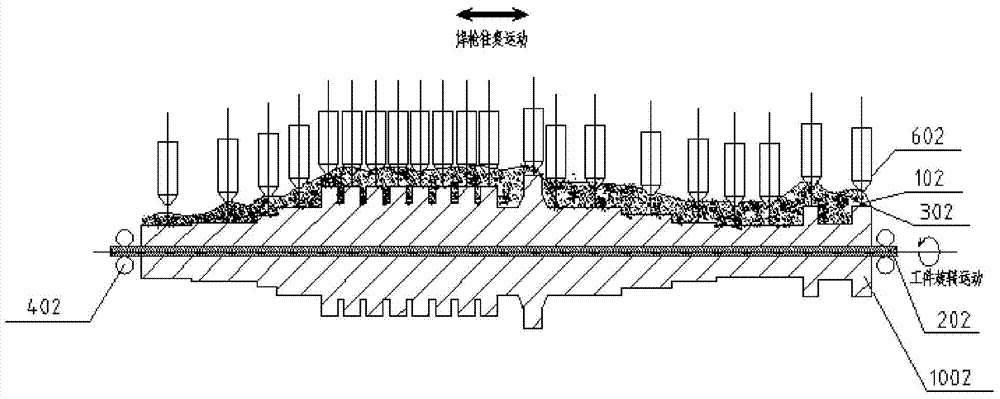
[0040] This example describes the manufacture of CPR1000 nuclear power conventional island integrated low-pressure rotor by horizontal submerged arc additive manufacturing method. The material is 30Cr2Ni4MoV, and the base material is 42CrMo rod. The equipment used includes:
[0041] (1) Swivel support platform;
[0042] (2) Welding power supply;
[0044] (4) Automatic wire feeding device;
[0045] (5) Automatic delivery of auxiliary materials and automatic recovery of auxiliary materials;
[0046] (6) Heating device;
[0047] (7) cooling device;
[0048] (8) Substrate;
[0049] (9) Control device.
[0050] figure 2 It is a schematic explanatory diagram for showing the submerged arc additive manufacturing method of this embodiment, and the power supply, automatic wire feeding device and other devices are omitted in the figure. The material power parameters are as follows:
[0051] 1) Choose welding wire 102, diameter 3mm, C content 0.15-0.1...
Embodiment 3
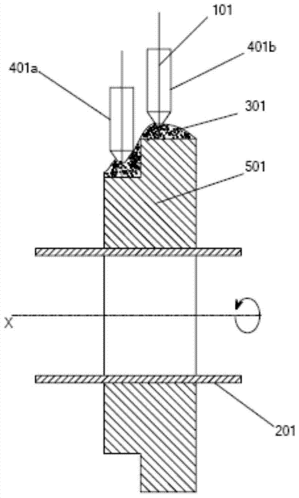
[0069] In this example, a tapered workpiece is vertically formed by submerged arc additive manufacturing. The material of the workpiece is RCC-M standard 18MnD5, and the material of the base material is Q235. The equipment used in this embodiment includes,
[0070] (1) Rotary support table; (2) Power supply; (3) Welding torch; (4) Automatic wire feeding device; (5) Flux automatic conveying and recovery device; (6) Flux blocking device; (7) Heating device; (8) ) cooling device; (9) substrate; (10) control device.
[0071] Figure 4 It is a schematic explanatory diagram showing the submerged arc additive manufacturing method of this embodiment, for the sake of simplification, the equipment is omitted in the figure. The selected parameters are: wire rod diameter 3mm, chemical composition C: 0.12-0.14%, the remaining elements are in accordance with the requirements of 18MnD5, the auxiliary material is the standard melting flux SJ101, the welding current is set to 600A, the weldi...
PUM
| Property | Measurement | Unit |
|---|---|---|
| diameter | aaaaa | aaaaa |
| thickness | aaaaa | aaaaa |
| diameter | aaaaa | aaaaa |
Abstract
Description
Claims
Application Information
 - R&D
- Intellectual Property
- Life Sciences
- Materials
- Tech Scout
- Unparalleled Data Quality
- Higher Quality Content
- 60% Fewer Hallucinations
Browse by: Latest US Patents, China's latest patents, Technical Efficacy Thesaurus, Application Domain, Technology Topic, Popular Technical Reports.
© 2025 PatSnap. All rights reserved.Legal|Privacy policy|Modern Slavery Act Transparency Statement|Sitemap|About US| Contact US: help@patsnap.com