Monolithic integration type multi-core optical fiber branching device and preparing method thereof

A multi-core optical fiber and single-core optical fiber technology, applied in the field of optical fiber, can solve the problems of large structure, difficult mass production, complicated operation and adjustment, etc., and achieve the effect of simple operation process, compact structure and low crosstalk.

Active Publication Date: 2015-04-22
GUILIN UNIV OF ELECTRONIC TECH
View PDF5 Cites 10 Cited by
  • Summary
  • Abstract
  • Description
  • Claims
  • Application Information

AI Technical Summary

Problems solved by technology

This method has low crosstalk and loss through precise operation and control, but the structure is large, the operation adju

Method used


Image

  • Monolithic integration type multi-core optical fiber branching device and preparing method thereof
  • Monolithic integration type multi-core optical fiber branching device and preparing method thereof
  • Monolithic integration type multi-core optical fiber branching device and preparing method thereof

Examples


Embodiment 1

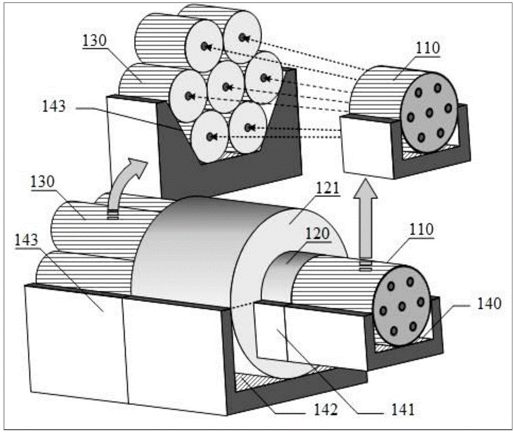
[0027] figure 1 It is a schematic diagram of the manufacturing method of a seven-core fiber splitter based on a self-focusing lens. The seven-core fiber 110, the self-focusing lens 120-121, and seven collimators with fiber ends (for clarity, not shown in the figure) are common single The mode fiber 130 is correspondingly placed in the laser etching grooves 140-143 on the quartz substrate. Slots 143-143 are made of high-precision CO 2 The laser is etched according to the set parameters: the length of the multi-core fiber rectangular groove line 140 is the design length of the multi-core fiber pigtail 110 inside the splitter, and the depth is equal to its radius; the self-focusing lens 120-121 has two different parameters The combination of self-focusing lens is used to spread the distance between the cores of the multi-core fiber 110 for imaging, corresponding to the core position of the single-mode fiber 130 with the same number of cores and similar core distribution. The length...

Embodiment 2

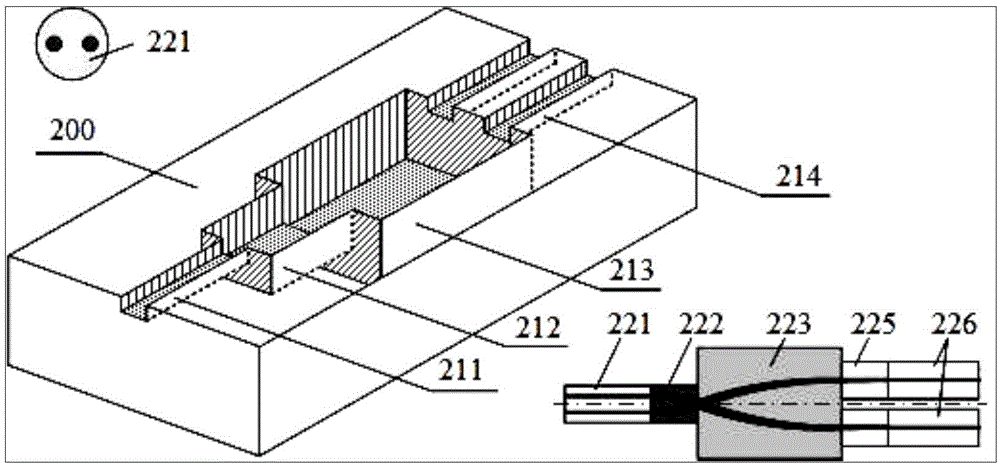
[0029] figure 2 It is a schematic diagram of the monolithic integrated design and manufacturing method of the dual-core optical splitter. Utilize high-precision CO 2 The laser etches the rectangular groove lines 211-214 on the quartz substrate 200 where the components 221-226 of the splitter are placed in batches. The groove line 211 corresponds to the dual-core fiber 221, and the groove line 212-213 corresponds to two different parameters. The self-focusing lenses 222-223 and the slot line 214 correspond to two single-mode optical fibers 226 with fiber-end collimators 225. The two-core optical channels of the symmetrical dual-core optical fiber 221 are separated from each other through the self-focusing lens groups 222-223, and are injected into the single-mode optical fiber 226 respectively. The depth of the groove line 211-214 is the radius of each component 221-226 of the splitter, and the width is the diameter. The groove line 211-214 is etched on the quartz substrate 200...

Embodiment 3

[0033] Figure 4 A top view of a dual-core fiber splitter with a single self-focusing lens is given, which is similar to Embodiment 2, except that a self-focusing lens 420 with a 0.25 pitch length is used. The output light from the core of the dual-core fiber 410 is obliquely emitted in the form of parallel beams at the center of the rear face after passing through the lens 420, and is transmitted in a uniform medium gap 440. The light beam is incident perpendicular to the center of the end face of the fiber end collimator 431, and is efficiently coupled into the single-mode fiber 430. The gap 440 may be filled with a refractive index matching liquid to reduce the light loss caused by end surface reflection. The single self-focusing lens 420 is used to spatially separate the light beams in different directions, and the length of the gap 440 and the alignment angle of the single-mode fiber 430 are required to have high accuracy, which greatly increases the difficulty of manufac...


PUM


Abstract

The invention belongs to the technical field of the optical fiber, and particularly relates to a monolithic integration type multi-core optical fiber branching device used for separating each single core optical fiber from the multi-core optical fiber and the preparing method of monolithic integration type multi-core optical fiber branching device. The monolithic integration type multi-core optical fiber branching device is formed by connecting a monolithic which is of the micro structure and prepared based on the multi-core optical fiber, a grin-lens or a grin-lens set and a single mode fiber corresponding to the number of cores with a micro collimator with fiber end. By means of the multi-core optical fiber branching device, the separation of each single core optical fiber from the multi-core optical fiber is achieved. The double grin-lens coupling system does not need to a rotary prism, so that the structure is more compact, the operating difficulty is greatly lowered and the manufacturing is simpler.

Description

Technical field [0001] The invention belongs to the technical field of optical fibers, and specifically relates to a monolithic integrated multi-core optical fiber splitter capable of separating the optical paths from a multi-core optical fiber to each single-core optical fiber and a manufacturing method thereof. Background technique [0002] As a typical space division multiplexing (SDM) solution, multi-core fiber (MCF) is most likely to be applied to optical fiber communications on a large scale due to its advantages of high density, low cost, and low energy consumption, which greatly increases transmission capacity. Various multi-core optical fibers play an irreplaceable and important role in the field of optical fiber sensing and integrated optical devices, but multi-core optical fibers face a challenge, that is, compatibility with existing systems, which requires the development of a reliable Multi-core optical fiber splitter with high performance, low loss, low interference...

Claims


Application Information

Patent Timeline
IPC IPC(8): G02B6/32
CPCG02B6/322
Inventor 苑立波陈宫傣
Owner GUILIN UNIV OF ELECTRONIC TECH
Why Eureka
Try Eureka