Direct drive permanent magnet wind generator, direct drive permanent magnet wind generator system and stator of direct drive permanent magnet wind generator

A technology of wind power generator and permanent magnet direct drive, which is applied in the direction of wind power generator, wind power motor combination, wind power generation, etc. It can solve the problems of affecting the service life, pressure resistance level and life reduction, and the inconvenience of wind power generating set, so as to extend the Effects of service life and insulation level reduction prevention

Active Publication Date: 2015-05-06
XINJIANG GOLDWIND SCI & TECH
View PDF6 Cites 20 Cited by
  • Summary
  • Abstract
  • Description
  • Claims
  • Application Information

AI Technical Summary

Problems solved by technology

[0006] The wind turbine outside the nacelle running outdoors is directly soaked by rain and snow melt, and a small amount of water enters the motor from the annular gap through the rotation of the motor; when the generator stops working in wet weather, moisture enters the generator Condensation occurs inside; generators that have been shut down for a long time are prone to moisture condensation due to moisture ingress; wind turbines working in harsh environments may also suffer from accidents such as rain, snow, and water immersion (drain holes are clogged), causing moisture to enter; generator production During the process, the moisture remaining in the insulation capillary is caused by not pre-baking according to the process requirements or not drying thoroughly after dipping, etc.
[0007] (2) The reason why the generator insulation is easy to be damp
[0012] (3) Hazards caused by moisture inside the generator
They can cause deterioration of insulation performance, lead to deterioration of electrical and mechanical properties of motor insulation, reduction of residual withstand voltage level and life, and eventually lead to insulation damage
[0034] (2) All of the above are operations of ground generator sets, and the operation at an altitude of 60-100 meters, including the realization of various functions, especially the maintenance of the engine room, is usually beyond the reach of manpower and material resources, and even becomes impossible
Some good methods used on the ground are inconvenient or even difficult to apply to wind turbines operating in the "sky"
[0035] (3) Relying on the above-mentioned hot air drying method alone is only a surface drying technology, which cannot solve the drying demand after the laminated layers inside the stator core are damp.
[0036] (4) The use of an open structure cannot resist the hazards of rain or snow intruding into the generator in windy and windy weather or in windy and snowy weather. The "reduced insulation level" pays for the cooling of the generator
[0037] (5) After shutdown, the humid air in the generator cavity and air gap condenses and infiltrates into the motor, which will cause the motor stator and the surface coating of the permanent magnet poles to be damp, which will affect their service life

Method used


Image

  • Direct drive permanent magnet wind generator, direct drive permanent magnet wind generator system and stator of direct drive permanent magnet wind generator
  • Direct drive permanent magnet wind generator, direct drive permanent magnet wind generator system and stator of direct drive permanent magnet wind generator
  • Direct drive permanent magnet wind generator, direct drive permanent magnet wind generator system and stator of direct drive permanent magnet wind generator

Examples


Embodiment 1

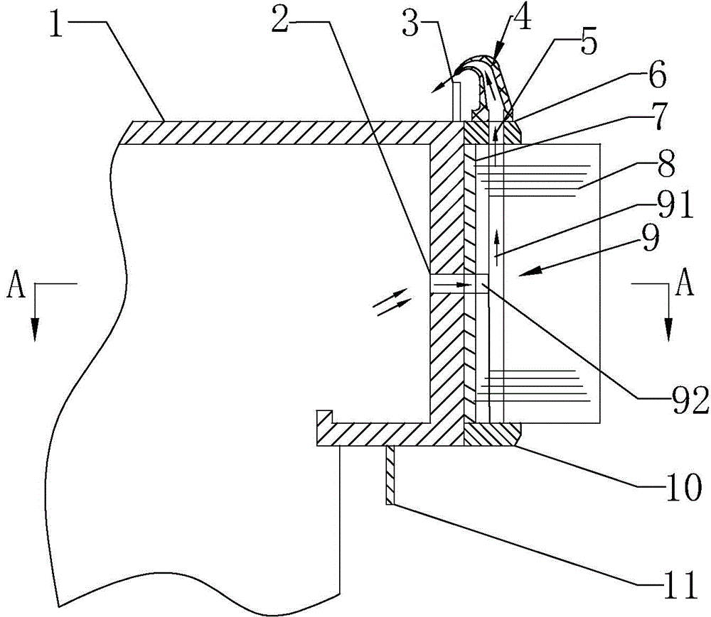
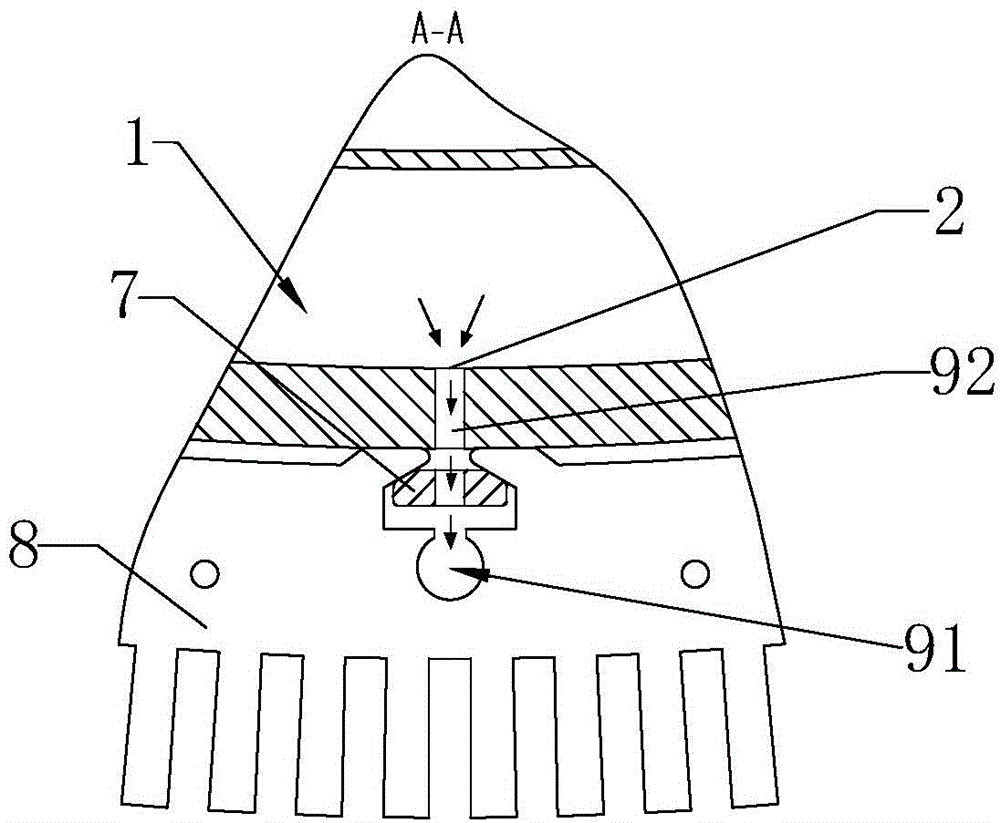
[0085] Such as figure 1 As shown, it is a schematic structural view of the stator of the permanent magnet direct drive wind power generator according to Embodiment 1 of the present invention. For ease of description, the figure 1 The upper part of the formula is defined as the propeller side (in the process of fan operation, the propeller side generally faces the upwind side), the lower part is defined as the tower side (in the process of fan operation, the tower side generally faces the downwind side), and the horizontal The direction is defined as radial direction (radial direction centering on the whole wind turbine), and the vertical direction is defined as axial direction (direction along the rotation axis of the wind turbine). In addition, the outer peripheral wall of the stator bracket refers to the side wall that is in contact with or adjacent to the stator core or the stamping key that fixes the stator core, that is, the outermost part of the stator bracket.

[0086...

Embodiment 2

[0115] The specific structure of the stator and permanent magnet direct drive wind power generator involved in this embodiment is as follows: Figure 7 and Figure 8 as shown, Figure 7 It is a structural schematic diagram of the stator and rotor joint part of the permanent magnet direct drive wind power generator according to the second embodiment of the present invention, Figure 8 It is a schematic diagram of the overall structure of the permanent magnet direct drive wind power generator according to the second embodiment of the present invention. For ease of description, the right side in the figure can be defined as the paddle side, the left side can be defined as the tower side, the vertical direction can be defined as the radial direction (the radial direction centered on the entire fan), and the horizontal direction can be defined as the axial direction ( along the direction of the wind turbine's axis of rotation). The small arrows shown in the figure represent the ...

Embodiment 3

[0143] The specific structure of the stator and the permanent magnet direct drive wind power generator involved in this embodiment, such as Figure 9 As shown, it is a structural schematic diagram of the stator and rotor joint part of the permanent magnet direct drive wind power generator of the third embodiment of the present invention. For the convenience of description, the right side in the figure can be defined as the paddle side (in the process of fan operation, The propeller side generally faces the upwind side), the left side is defined as the tower side (in the process of fan operation, the propeller side generally faces the downwind side), and the vertical direction is defined as the radial direction (taking the entire fan as the center The radial direction), the horizontal direction is defined as the axial direction (the direction along the rotation axis of the wind turbine). The small arrows shown in the figure represent the flow path of the airflow. The following...


PUM


Abstract

The invention provides a direct drive permanent magnet wind generator, a direct drive permanent magnet wind generator system and a stator of the direct drive permanent magnet wind generator. The stator comprises a stator support, a stator iron core arranged on the peripheral wall of the stator support, and a paddle side tooth support, wherein the paddle side tooth support is arranged on the paddle side axial end face of the stator iron core, at least one air hole is formed in the peripheral wall of the stator support, and at least one second air hole is formed in the paddle side tooth support. The stator further comprises at least one air flow passageway used for communicating the first air holes with the second air holes, wherein the air flow passageways penetrate through the stator iron core. The micro-positive pressure technology is used in the stator and a rotor of the airborne wind turbine, and therefore a motor can dry itself in a self-adaption mode, external severe air flow is prevented from entering the motor, the service life of permanent magnet poles is prolonged, the insulation level reduction of devices inside the motor is prevented, the risk that the motor is corroded by severe air flow is lowered, and the insulation reliability is improved.

Description

technical field [0001] The invention belongs to the technical field of wind power, and in particular relates to a permanent magnet direct drive wind power generator, a system and a stator thereof. Background technique [0002] In the prior art, the open type permanent magnet direct drive external rotor wind turbine relies on natural air cooling, and the open structure is conducive to natural ventilation and heat exchange, which helps to use permanent magnet materials for the magnetic poles to prevent the magnetic degradation after the temperature rise exceeds the standard, but the generator is usually exposed. Under extremely harsh environmental conditions (exposed to wind, frost, rain, snow, sand, salt spray, etc.). [0003] 1. Sources and hazards of moisture inside the motor in a humid environment [0004] (1) Source of moisture [0005] In a humid environment, rain and snow are more likely to enter the motor than in a normal environment. In summary, the main sources of ...

Claims


Application Information

Patent Timeline
Patent Type & Authority Applications(China)
IPC IPC(8): H02K1/18H02K1/20H02K1/22H02K5/10
CPCH02K1/187H02K1/20H02K9/08H02K5/207H02K5/10H02K9/02H02K15/125F05B2220/7068F03D80/60F03D9/25H02K7/1838H02K9/04Y02E10/72
Inventor 王栋马盛骏李延慧刘承前赵祥
Owner XINJIANG GOLDWIND SCI & TECH
Why Eureka
Try Eureka