Double-tube vacuum film sperm separation method and separation device

A separation device and vacuum film technology, applied in the field of cell biology, can solve the problems affecting semen separation and processing, low recovery rate, etc., and achieve the effects of improving sperm yield, high recovery rate and ensuring quality

Inactive Publication Date: 2015-05-27
张丽红
View PDF5 Cites 8 Cited by
  • Summary
  • Abstract
  • Description
  • Claims
  • Application Information

AI Technical Summary

Problems solved by technology

In practice, we found that the liquefied semen can be obtained by passing the non-liquefied human semen through filter paper and centrifuging, but it is diffic

Method used


Image

  • Double-tube vacuum film sperm separation method and separation device
  • Double-tube vacuum film sperm separation method and separation device

Examples


Embodiment 1

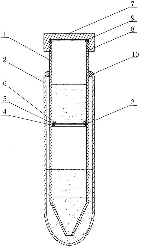
[0039]Embodiment 1: A sperm separation device according to the present invention, the main structure includes a centrifuge inner tube 1 and a centrifuge tube 2 . The centrifuge tube 2 adopts a centrifuge tube 2 with a specification of 15ml, and the centrifuge inner tube 1 is placed in the centrifuge tube 2 . The middle and upper part of the centrifuge inner tube 1 is a cylindrical structure with a tube wall thickness of 0.5 mm, an outer diameter of 13 mm and a length of 95 mm. It can be matched with the centrifuge tube 2 of 15ml specification. The lower part of the centrifuge inner tube 1 is a conical structure with an opening at the tip, so that the separated sperm clusters can be concentrated in the center of the bottom of the centrifuge inner tube 1, and the separated sperm clusters can be separated from the centrifugal tube 1 and the centrifuge tube 2. Leave the bottom of the centrifuge tube 2 through the opening. And the bottom diameter of the lower cone is 13mm, the ti...

Embodiment 2

[0050] Embodiment 2: A sperm separation device according to the present invention, the main structure includes a centrifuge inner tube 1 and a centrifuge tube 2 . The centrifuge tube 2 adopts a centrifuge tube 2 with a specification of 10ml, and the centrifuge inner tube 1 is placed in the centrifuge tube 2 . The middle and upper part of the centrifuge inner tube 1 is a cylindrical structure with an upper diameter and a lower diameter, and its outer diameter is 13 mm, upper end inner diameter is 12 mm, lower end inner diameter is 11 mm, and length is 100 mm. It can be matched with the centrifuge tube 2 of 10ml specification. The lower part of the centrifuge inner tube 1 is a conical structure with an open tip, so that the separated sperm clusters can be concentrated in the center of the bottom of the centrifuge inner tube 1, and the separated sperm clusters are separated from the centrifuge tube 1 and the centrifuge tube 2. It can stay at the bottom of the centrifuge tube 2 t...


PUM

PropertyMeasurementUnit
Bottom diameteraaaaaaaaaa
Diameteraaaaaaaaaa

Abstract

The invention discloses a double-tube vacuum film sperm separation method and a separation device and mainly relates to the field of cytobiology. The separation device comprises an inner centrifugal tube and a centrifugal tube, wherein the lower part of the inner centrifugal tube is of a cone structure which is opened at the tip; a filter device is mounted in the inner centrifugal tube; an inner tube seal cover is arranged at the orifice at the top of the inner centrifugal tube. By using the device to separate a seminal fluid, a density gradient solution is prepared by adopting a classical density gradient sperm separation method and a sperm lotion and sperms are sequentially dropped onto the filter device, and the inner centrifugal tube after low-speed centrifugal treatment is taken out, so that the inner centrifugal tube a is separated from the centrifugal tube, and the residues in the centrifugal tube are part of alpha% density gradient solution and bottom spermatia. The method and device disclosed by the invention have the beneficial effects that whether the seminal fluid is liquefied or not, seminal plasma and sperms are thoroughly separated through a simple operation; the damage on sperms in the pre-treatment process of the seminal fluid is avoided; the success rate, the recovery rate and the quality of sperms are excellent.

Description

technical field [0001] The invention relates to the field of cell biology, in particular to a double-tube vacuum membrane sperm separation method and a device. Background technique [0002] Sperm separation processing technology is an indispensable key technology in assisted reproductive technology. The commonly used sperm separation technology in the implementation of assisted reproductive technology mainly includes density gradient centrifugation technology and upstream separation method. Each of these techniques has its own limitations. The sperm recovery rate of the density gradient centrifugation technique is relatively high, but after the treatment is completed, the upper impurities and low-density solution need to be removed with a straw, and then the sperm at the bottom of the centrifuge tube is sucked through the liquid surface of the high-density solution with a straw. It adheres to the wall of the centrifuge tube and flows downstream to the liquid surface of the ...

Claims


Application Information

Patent Timeline
IPC IPC(8): C12M1/24C12N5/076
CPCC12M29/04C12M45/05C12N5/061C12M47/04
Inventor 张丽红杨慧吕淑君王秋菊赵俭张艳萍张伟董云玲宋霞
Owner 张丽红
Why Eureka
Try Eureka