Iron-carbon micro-electrolysis device and use method thereof
A technology of iron-carbon micro-electrolysis and micro-electrolysis tower, applied in chemical instruments and methods, degassed water/sewage treatment, water/sludge/sewage treatment, etc., can solve iron-carbon bed blockage, unsuitable control, and pollution bubbles and other problems, to reduce negative effects, increase agitation and friction, and strengthen the control of foam
- Summary
- Abstract
- Description
- Claims
- Application Information
AI Technical Summary
Problems solved by technology
Method used
Image
Examples
Embodiment 1
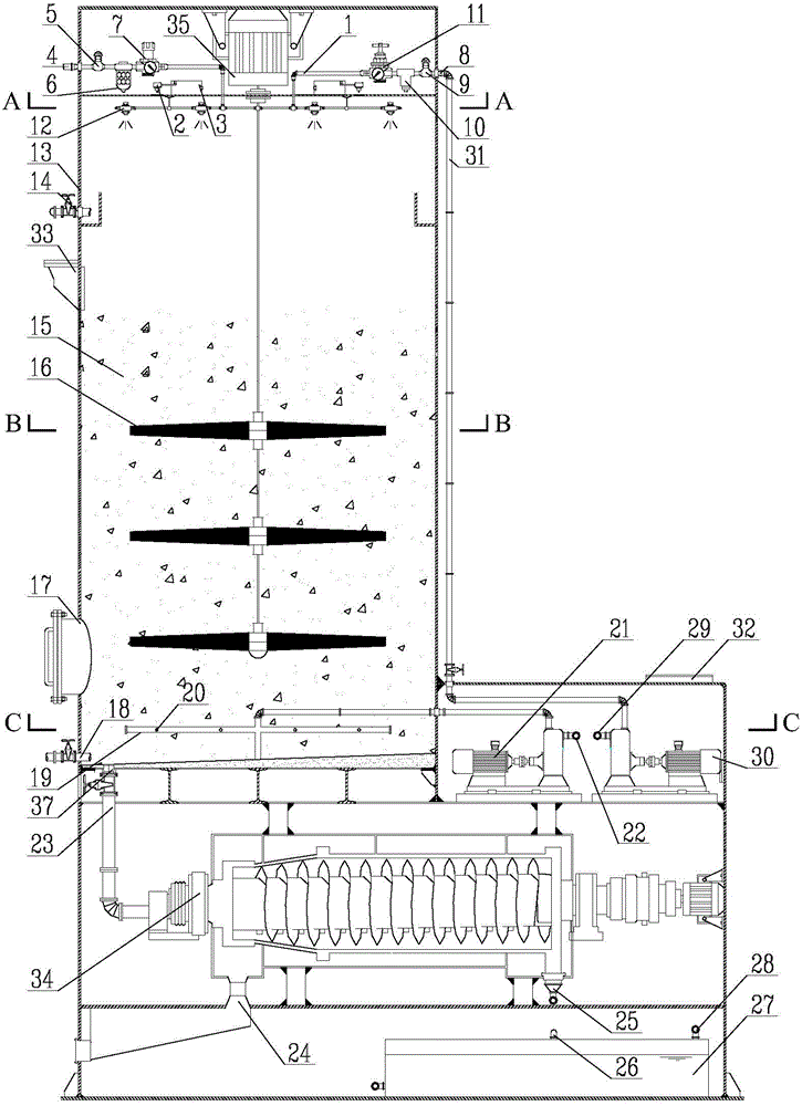
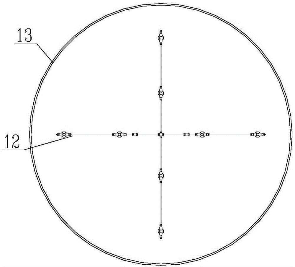
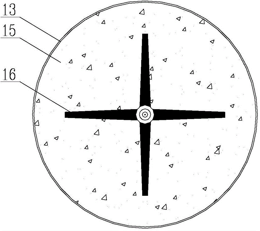
[0036] Such as figure 1 , figure 2 , image 3 and Figure 4 As shown, a kind of iron-carbon micro-electrolysis device comprises pressure atomization system 1, micro-electrolysis tower 13, stirring impeller 16, water distribution system, water storage tank 27, centrifugal dehydrator 34 and control system, and pressure atomization system 1 includes Air system, water inlet system, infrared transmitter and receiver 2, integrated module 3 and air atomizing nozzle 12, the air intake system includes air inlet 4, air shut-off valve 5, air filter 6 and air conditioning Valve 7; the water inlet system includes a return water inlet 8, a liquid shut-off valve 9, a liquid filter 10 and a liquid regulating valve 11 connected sequentially through pipelines; one end of the air regulating valve 7, one end of the liquid regulating valve 11, infrared emission and receiving Both the device 2 and the integrated module 3 are connected to the air atomizing nozzle 12, and there are 8 air atomizin...
Embodiment 2
[0045] With embodiment 1, difference is: air atomization nozzle 12 has 12; The aspect ratio of micro electrolysis tower 13 is 8:1 (diameter is 1m, and effective height is 8m); The volume of iron-carbon filler 15 is micro 1 / 2 of the volume of the electrolytic tower 13, the iron-carbon mass ratio in the iron-carbon filler 15 is 3:1; the stirring impeller 16 is provided with 5 layers;
[0046] In this embodiment, a certain dye mother liquor wastewater (water quality is COD: 10000-14000mg / L, BOD 5 / COD: 0.04-0.06, pH: 2.0-2.5, chroma: 14000-16000 times) as an example for wastewater treatment.
[0047] Its processing step is the same as embodiment 1, and the difference is: in the step (1), the influent flow rate is 3.2m 3 / h, the water intake time is 0.5h, and the rotating speed of the stirring impeller during water intake is 360r / min; the rotating speed of the stirring impeller after entering the reaction stage in the step (2) is 1080r / min, and the reaction time is 2.5h; step (3)...
Embodiment 3
[0050] With embodiment 1, difference is: air atomization nozzle 12 has 8; The aspect ratio of micro electrolysis tower 13 is 5:1 (diameter is 1m, and effective height is 5m); The volume of iron-carbon filler 15 is micro 1 / 3 of the volume of the electrolytic tower 13, the iron-carbon mass ratio in the iron-carbon filler 15 is 2:1; the stirring impeller 16 is provided with 3 layers;
[0051] In this embodiment, silk dyeing and printing wastewater (chroma 800 times, COD: 1400 mg / L, pH: 5.3-5.5) is taken as an example for wastewater treatment.
[0052] Its processing step is the same as embodiment 1, and the difference is: in the step (1), the influent flow rate is 3.2m 3 / h, the water intake time is 0.5h, and the rotating speed of the stirring impeller during water intake is 360r / min; the rotating speed of the stirring impeller after entering the reaction stage in the step (2) is 1080r / min, and the reaction time is 1.5h; step (3) The medium standing time is 0.5h. After being tr...
PUM
| Property | Measurement | Unit |
|---|---|---|
| Particle size | aaaaa | aaaaa |
Abstract
Description
Claims
Application Information
 - R&D
- Intellectual Property
- Life Sciences
- Materials
- Tech Scout
- Unparalleled Data Quality
- Higher Quality Content
- 60% Fewer Hallucinations
Browse by: Latest US Patents, China's latest patents, Technical Efficacy Thesaurus, Application Domain, Technology Topic, Popular Technical Reports.
© 2025 PatSnap. All rights reserved.Legal|Privacy policy|Modern Slavery Act Transparency Statement|Sitemap|About US| Contact US: help@patsnap.com


