System for performing power generation by utilizing liquid thermoelectric effect

A technology of thermoelectric power generation and liquid, which is applied in the direction of generators, generators/motors, and electrical components that convert kinetic energy into electrical energy. It can solve the problems of no electrical energy output and the inability to form net charges, and achieve improved efficiency, simple structure, and reduced The effect of flow loss

Inactive Publication Date: 2015-07-29
WUHAN UNIV
View PDF6 Cites 10 Cited by
  • Summary
  • Abstract
  • Description
  • Claims
  • Application Information

AI Technical Summary

Problems solved by technology

The research on liquid thermoelectricity is still almost blank. The main reason is that in solids, the temperature gradient will drive negatively charged electrons to move in one direction, and the movement of a single charge will form electrical energy; while in liquids, The

Method used


Image

  • System for performing power generation by utilizing liquid thermoelectric effect
  • System for performing power generation by utilizing liquid thermoelectric effect
  • System for performing power generation by utilizing liquid thermoelectric effect

Examples


Embodiment 1

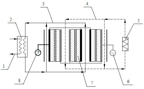
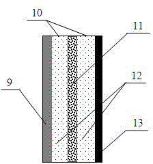
[0034] see figure 1 , using a single liquid thermoelectric power generation unit, the ion exchange membrane described in the power generation unit is an alumina nanoporous membrane with a diameter of 25 mm, a pore diameter of 100 nm, a height of 60 μm, and a porosity of about 60%. The negative pole of the power generation unit is a silver electrode, and the power generation unit The positive pole is a silver chloride electrode, and the electrolyte solution is 10 -4 mol / L sodium chloride solution, the working medium of the low-temperature circulation loop is a mixture of ice and water, and the working medium of the high-temperature circulation loop is water. The hot circulating water flows through the positive electrode (silver chloride electrode) side of the power generation unit, and the cold ice water flows through the negative electrode (silver electrode) side of the power generation unit. The structural characteristics of other parts are the same as figure 1 same. Since ...

Embodiment 2

[0036] see figure 1 , using a single liquid thermoelectric power generation unit, the ion exchange membrane described in the power generation unit is an anodized aluminum nanoporous membrane with a diameter of 25mm, a pore diameter of 100nm, a height of 60μm, and a porosity of about 60%. The electrode is a standard silver-chloride Silver electrode pair, electrolyte solution is 10 -2 mol / L potassium chloride solution, the working fluid of the low-temperature circulation loop is ice-water mixture, and the working medium of the high-temperature circulation loop is hot water at 60 ° C. The structural characteristics of other parts are the same as figure 1 same. After the system works stably, it is detected that its output current is 27.8μA.


PUM

PropertyMeasurementUnit
Diameteraaaaaaaaaa
Apertureaaaaaaaaaa
Heightaaaaaaaaaa

Abstract

The invention discloses a system for performing power generation by utilizing a liquid thermoelectric effect. The system consists of a high-temperature circulation loop, a liquid thermoelectric power generation system and a low-temperature circulation loop; the high-temperature circulation loop is provided with a heat exchanger; heat exchange is performed between low-temperature heat energy in a factory or an environment and a thermal circulation working medium in the heat exchanger; a condenser is arranged in the low-temperature circulation loop; a low-temperature circulation working medium is cooled in the condenser; when an ion exchange membrane is an anion-exchange membrane, the high-temperature circulation loop and the low-temperature circulation loop respectively pass the anode and the cathode of a liquid thermoelectric power generation unit. The system disclosed by the invention has lower requirement on the temperature of the heat energy, can normally operate as long as two ends of the liquid thermoelectric power generation unit have temperature difference, and has a great prospect in the recycling aspect of power plant and factory waste heat and seawater low-temperature heat energy; moreover, the system disclosed by the invention is higher in utilization efficiency of the heat energy, lower in cost and extremely environment friendly.

Description

technical field [0001] The invention relates to a temperature difference power generation system, in particular to a system for generating electricity by collecting waste heat from power plants and factories and seawater temperature difference heat energy by using liquid thermoelectric effect. Background technique [0002] Energy is an important material basis for human development. With the advancement of science and technology and the continuous improvement of people's living standards, the fossil energy that the world mainly relies on is being exhausted, and the energy crisis is approaching step by step. At the same time, the use of a large amount of fossil fuels has also caused global environmental pollution and damage to the ecological environment. Therefore, it is imperative to develop more advanced energy conversion methods to improve energy utilization efficiency and vigorously develop clean and renewable energy. [0003] There is a large amount of energy in our li...

Claims


Application Information

Patent Timeline
IPC IPC(8): H02N3/00
Inventor 胡雪蛟李昌铮王琪单源鸿
Owner WUHAN UNIV
Why Eureka
Try Eureka