Quasi-proportional resonance control-based permanent magnet synchronous motor parameter identification system and method

A permanent magnet synchronous motor, quasi-proportional resonance technology, used in control systems, control generators, vector control systems, etc., can solve problems such as voltage injection method overcurrent, reduce current harmonic content, strong versatility, The effect of preventing overcurrent problems

Active Publication Date: 2015-07-29
HARBIN INST OF TECH
View PDF5 Cites 23 Cited by
  • Summary
  • Abstract
  • Description
  • Claims
  • Application Information

AI Technical Summary

Problems solved by technology

[0006] In order to solve the problem of overcurrent in the voltage injection method, the present invention now provides a perman

Method used


Image

  • Quasi-proportional resonance control-based permanent magnet synchronous motor parameter identification system and method
  • Quasi-proportional resonance control-based permanent magnet synchronous motor parameter identification system and method
  • Quasi-proportional resonance control-based permanent magnet synchronous motor parameter identification system and method

Examples


specific Embodiment approach 1

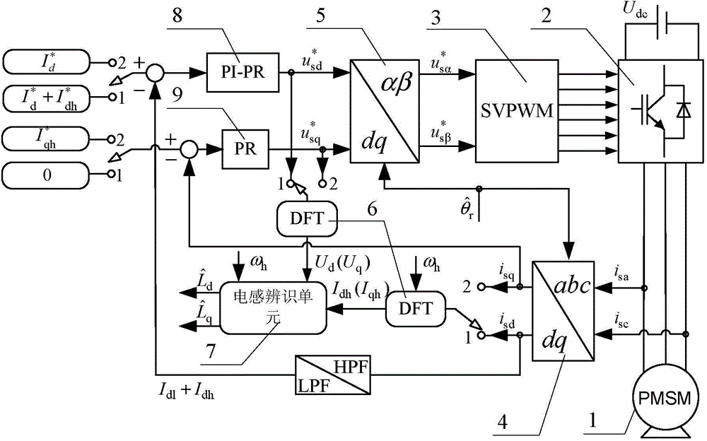
[0043] Specific implementation mode one: refer to figure 1 This embodiment is described in detail. The permanent magnet synchronous motor inductance parameter identification system based on quasi-proportional resonance control described in this embodiment includes: a voltage source inverter 2, a space vector pulse width modulation unit (SVPMW) 3, a three-phase - Stationary coordinate transformation unit 4, rotating-stationary coordinate transformation unit 5, two discrete Fourier analysis (DFT) units 6, inductance identification unit 7, proportional-integral-quasi-proportional resonant (PI-PR) controller 8 and quasi-proportional Resonant (PR) controller 9;

[0044] The current sensor is used to collect the current signal of the input terminal of the permanent magnet synchronous motor 1, the a-phase stator current signal output terminal of the current sensor is connected to the a-phase stator current signal input terminal of the three-phase-stationary coordinate transformation ...

specific Embodiment approach 2

[0066] Specific embodiment two: This embodiment is a further description of the permanent magnet synchronous motor inductance parameter identification system based on quasi-proportional resonance control described in specific embodiment one. In this embodiment,

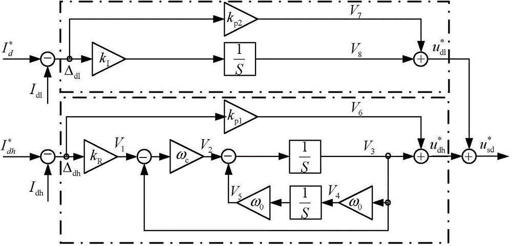
[0067] The current fundamental frequency amplitude signal includes: the current fundamental frequency amplitude signal of the q-axis current feedback signal and the current fundamental frequency amplitude signal of the d-axis current feedback signal;

[0068] The voltage fundamental frequency amplitude signal includes: the voltage fundamental frequency amplitude signal of the q-axis voltage given signal and the voltage fundamental frequency amplitude signal of the d-axis voltage given signal;

[0069] The d-axis current feedback signal includes: d-axis DC current feedback signal and d-axis AC current feedback signal;

[0070] d-axis current given signal includes: d-axis dc bias signal and d-axis ac given signal;

[0...

specific Embodiment approach 3

[0074] Embodiment 3: This embodiment is to further explain the permanent magnet synchronous motor inductance parameter identification system based on quasi-proportional resonance control described in Embodiment 1. In this embodiment, it also includes: a current sensor;

[0075] The current sensor is used to collect the a-phase current signal and the c-phase current signal of the permanent magnet synchronous motor 1 , and the current signal output end of the current sensor is connected to the current signal input end of the three-phase-stationary coordinate transformation unit 4 .


PUM


Abstract

A quasi-proportional resonance control-based permanent magnet synchronous motor parameter identification system and method belongs to the field of motor control. The quasi-proportional resonance control-based permanent magnet synchronous motor parameter identification system and method solves the problem of overcurrent existing a voltage injection method. According to the quasi-proportional resonance control-based permanent magnet synchronous motor parameter identification system and method, by designing the parameters of a proportional coefficient Kp2 and an integral coefficient KI of a proportional-integral link, closed-loop control of DC (direct current) components of injected composite signals can be achieved; by reasonably designing the quasi-proportional gain coefficient Kp1, the integral gain coefficient KR and the cut-off frequency omega c of a quasi-proportional resonance controller, the quasi-proportional resonance controller can achieve floating control of high-frequency sinusoidal signals in the injected composite signals nearby the resonant frequency omega 0; a proportional-integral-quasi-proportional resonance controller can accurately control the value of the injected composite current signals, reduce the harmonic content of current and meanwhile avoid the problem of overcurrent possibly occurring during inductance parameter identification experiments through the voltage injection method, thereby being applicable to different types of motors and high in universality.

Description

technical field [0001] The invention belongs to the field of motor control, and in particular relates to a permanent magnet synchronous motor inductance parameter identification technology based on quasi-proportional resonance. Background technique [0002] Compared with traditional induction motors, permanent magnet synchronous motors are composed of stator windings and permanent magnet rotors, and have the advantages of simple structure, reliable operation, high power density, and good speed regulation performance. In the permanent magnet synchronous motor drive system, in order to enhance the versatility of the inverter, it is necessary to obtain the motor parameters such as motor inductance and resistance before the motor runs to realize the self-tuning of the controller PI parameters and optimize the motor control strategy to achieve excellent anti-load disturbance performance and dynamic responsiveness. [0003] For the speed sensorless vector control system, it is ne...

Claims


Application Information

Patent Timeline
IPC IPC(8): H02P21/14
Inventor 王高林丁力杨雷王莹袁碧荷付炎徐殿国
Owner HARBIN INST OF TECH
Why Eureka
Try Eureka