Device for self-nanometerization of the surface of rod-shaped metal materials
A metal material, self-nanoization technology, applied in the field of metal material processing, can solve the problems of inability to handle complex shape test pieces, difficulty in working on the back of the test piece, difficulty in ensuring uniformity, etc., to achieve simple and practical equipment construction, uniform processing quality, Overcome the effect of uniform surface treatment
- Summary
- Abstract
- Description
- Claims
- Application Information
AI Technical Summary
Problems solved by technology
Method used
Image
Examples
Embodiment 1
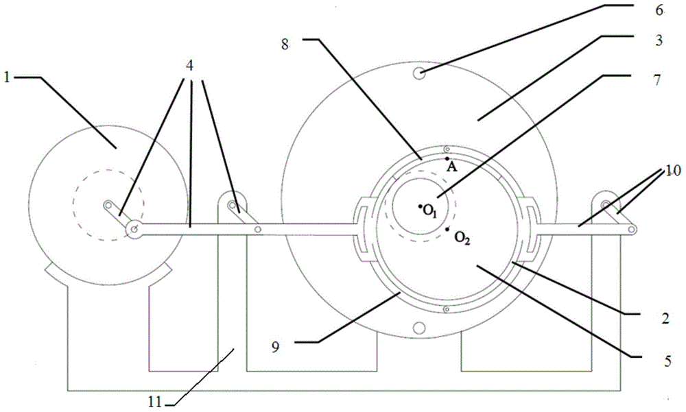
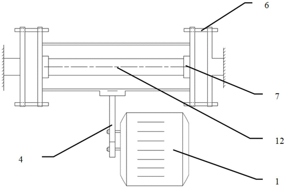
[0040] Such as Figure 1-5 , as shown in 9, the rod-shaped metal material surface self-nanometerization device includes a metal cylinder 2, a driving device, baffles 3 on both sides, a screw tightening device 6, clamps 7 on both sides, and projectiles 5;
[0041] The metal cylinder 2 is integrally ring-shaped and has no bottom surface. Its opening surface is in smooth and close contact with the baffles 3 on both sides so that a closed space is formed between the metal cylinder and the baffles on both sides. The screw tightening device 6 is used to adjust the The distance between the baffles, so that the metal cylinder 2 can be embedded and attached to the baffles 3 on both sides. The metal cylinder is provided with an opening device 8 and a lock ring 9. The opening device 8 is used to load the projectile 5, and the lock ring 9 is used to fix the opening device 8 on the metal cylinder 2 after loading the projectile, and the diameter of the projectile 5 is 0.8-3mm;
[0042] The...
Embodiment 2
[0049] Such as Figure 6-10 As shown, the self-nanometerization device on the surface of the rod-shaped metal material includes a metal cylinder 2, a driving device, baffles 3 on both sides, a screw tightening device 6, clamps 7 on both sides, and projectiles 5;
[0050] The clamps 7 on both sides are respectively attached to the baffle plates 3 on both sides, and are used to clamp the rod-shaped metal to be processed, and the distance between the clamps on both sides is adjustable;
[0051] The driving device drives the metal cylinder 2 to deviate a little from the center of the circle around the inside of the cylinder. 1 Do high-speed revolution, O 1 At the same time, it is also the axis of the bar metal to be processed;
[0052] Described driving device comprises frequency conversion motor 1, V-belt 15, eccentric turntable 16, vertical slider 17, vertical slider device 18, horizontal slider 19, horizontal slider device 20, described eccentric turntable 16 inner side is pr...
Embodiment 3
[0057] The surface nano-processing of the rod-shaped metal is completed using the device in Example 1.
[0058] Rod-shaped metal material: a light round steel bar Q235B with a diameter of 16mm and a length of 200mm. Main elements: Content Carbon C: ≤0.12%~0.20%; Silicon Si: ≤0.3%; Manganese Mn: ≤0.3%~0.7%; Sulfur S: ≤0.045%; Phosphorus P: ≤0.045%; Content ≤ 0.30%; Nickel Ni: Allowable residual content ≤ 0.30%; Copper Cu: Allowable residual content ≤ 0.30%.
[0059] Equipment: The device adopts YVP132S-4-5.5KW variable frequency speed regulating motor, which is used to drive the four-bar transmission mechanism of the hinge, so that the connecting rod drives the metal cylinder to perform high-speed revolution. The horizontally placed metal cylinder and the opening device are made of H13 hot work die steel, prepared by machining and heat treatment, with a hardness of HRC56. The metal cylinder has a radius dimension of 9 cm and a thickness of 1 cm. The smooth contact parts betw...
PUM
| Property | Measurement | Unit |
|---|---|---|
| radius | aaaaa | aaaaa |
| diameter | aaaaa | aaaaa |
| radius | aaaaa | aaaaa |
Abstract
Description
Claims
Application Information
 - R&D
- Intellectual Property
- Life Sciences
- Materials
- Tech Scout
- Unparalleled Data Quality
- Higher Quality Content
- 60% Fewer Hallucinations
Browse by: Latest US Patents, China's latest patents, Technical Efficacy Thesaurus, Application Domain, Technology Topic, Popular Technical Reports.
© 2025 PatSnap. All rights reserved.Legal|Privacy policy|Modern Slavery Act Transparency Statement|Sitemap|About US| Contact US: help@patsnap.com


