Method for preparing high-density cemented-carbide part with complicated shape and cutter

A cemented carbide and complex shape technology, applied in the field of powder metallurgy, can solve the problems of low cemented carbide powder content, inability to completely eliminate pores, and low product density, so as to increase the density of the green body, save raw materials, and improve production efficiency Effect

Inactive Publication Date: 2015-09-16
UNIV OF SCI & TECH BEIJING
View PDF5 Cites 29 Cited by
  • Summary
  • Abstract
  • Description
  • Claims
  • Application Information

AI Technical Summary

Problems solved by technology

However, when the cemented carbide parts are injected into the blank body of the slurry, the content of the cemented carbide powder in the slurry is low, and a large number of pores are left after ...

Method used


Image

  • Method for preparing high-density cemented-carbide part with complicated shape and cutter

Examples


Embodiment 1

[0027] Implementation example 1 (tungsten cobalt 10X cemented carbide angle milling cutter)

[0028] 3D printing negative mold: Use 3D modeling software to design the negative mold model of the angle milling cutter, enlarge the three-dimensional mold model by 120% according to the actual post-shrinkage situation, and perform layered slice processing on the negative mold model of the angle milling cutter. Imported into the 3D printing equipment, using ABS plastic wire as the printing material, 3D printing out the hollow and thin-walled angle milling cutter mold;

[0029] Prepare the slurry: mix the organic monomer hydroxyethyl methacrylate (HEMA) and the solvent toluene at a ratio of 1:1, add 0.01wt% catalyst benzoyl peroxide (BPO), stir evenly to form a premix , add tungsten-cobalt 10X cemented carbide powder with an average particle size of 2 μm, stir fully to make a slurry with a solid phase content of 55vol%, add 0.01wt% dispersant to improve the fluidity of the slurry, and...

Embodiment 2

[0033] Implementation example 2 (tungsten cobalt 6 hob)

[0034] 3D printing negative mold: Use 3D modeling software to design the negative mold model of the tungsten-cobalt 6 hob, and enlarge the three-dimensional mold model by 160% according to the actual post-shrinkage situation, and layer the negative mold model of the hob Slicing processing, imported into the 3D printing equipment, using PLA plastic filament as the printing material, 3D printing out the hollow and thin-walled hob negative mold;

[0035] Prepare the slurry: mix the organic monomer acrylamide and the crosslinking agent N,N'-methylenebisacrylamide according to the mass ratio of 15:1, dissolve them in deionized water, stir until dissolved, and prepare the organic monomer Concentration of 20wt% to 25wt% of the premixed solution, adding tungsten-cobalt 6 cemented carbide powder with an average particle size of 5 μm, stirring fully to make a slurry with a solid phase content of 48%, adding 0.03wt% dispersant to ...


PUM

PropertyMeasurementUnit
Granularityaaaaaaaaaa

Abstract

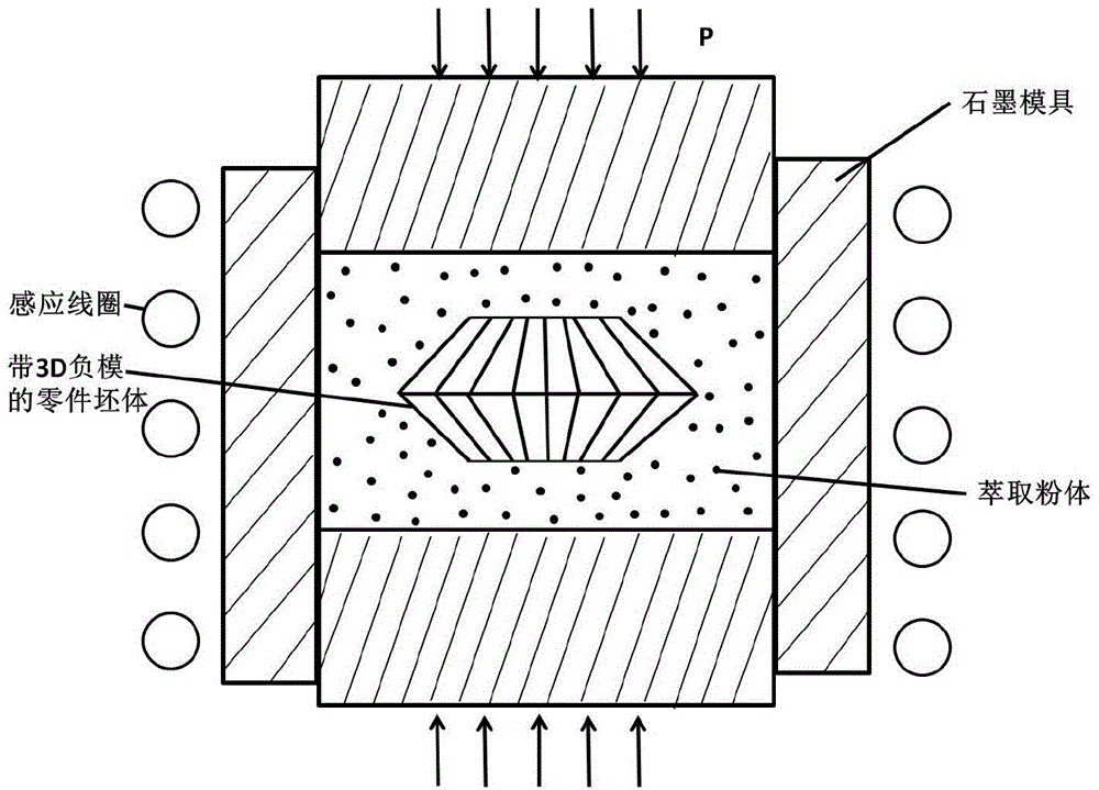
The invention provides a method for preparing high-density cemented-carbide part with a complicated shape and a cutter. In combination of 3D print technology, slurry injection and extraction of powder pressure, a negative mold of the part with the hollow thin wall can be made via 3D print technology. Slurry containing tungsten-cobalt type alloy is injected into the negative mold of the part and then cured in order to obtain a part blank made by tungsten-cobalt type alloy. By means of extraction of powder pressure and hot-pressed sintering, the high-density cemented-carbide part with the complicated shape and the cutter are made. The method for preparing the high-density cemented-carbide part with the complicated shape and the cutter has following beneficial effects: the method gives full play to advantages of arbitrary forming and high relative density of 3D printing and helps to overcome the defects that the mold (a force-transmitting medium) with the complicated shape by adoption of hot-pressing, cold-isostatically pressing, hot-isostatic pressing is difficult to manufacture and low density and easy cracking and deformation of a blank body by adoption of conventional pressureless sintering and negative pressure sintering; and a high-relative-density cemented-carbide product with arbitrary complicated shapes can be prepared.

Description

technical field [0001] The invention belongs to the technical field of powder metallurgy and relates to a manufacturing technology of cemented carbide parts, in particular, it provides a method of manufacturing high-density and complex-shaped cemented carbide parts and cutting tools combined with technologies such as 3D printing, slurry casting and powder pressure extraction. Methods. Background technique [0002] About 65 years ago, countries such as the United States and Western Europe began to refer to China's ceramic industry, making metal powder into a slurry with certain fluidity, and then pouring it into a hollow negative mold. After the slurry solidified, a metal with a special shape was obtained. blank. The blank is sintered at high temperature to obtain a "cermet" product with a certain density and a certain shape. This process has the advantages of forming a body of arbitrary complex shape and high utilization rate of raw materials. This achievement seems to ma...

Claims


Application Information

Patent Timeline
IPC IPC(8): B22F3/22B22F3/16
Inventor 郭志猛吴成义张欣悦柏鉴玲叶青王贤郭雷辰
Owner UNIV OF SCI & TECH BEIJING
Why Eureka
Try Eureka