Direct coal liquefaction oil hydrogenation stabilization method
A technology of direct coal liquefied oil and liquefied oil, which is applied in the direction of refining to remove heteroatoms, etc., can solve the problems of high investment cost, high energy consumption in operation, and huge hydrogenation equipment, so as to reduce investment cost and energy consumption in operation, and improve effective Throughput, downscaling effects
- Summary
- Abstract
- Description
- Claims
- Application Information
AI Technical Summary
Problems solved by technology
Method used
Image

Examples
Embodiment 1
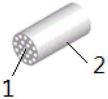
[0064] The properties of the coal direct liquefied oil used in this example are listed in Table 1, and the hydrogenation catalyst used is a catalyst named HDO-2 produced by Hunan Changling Petrochemical Technology Company. This embodiment adopts Figure 5 The process shown hydrotreats coal direct liquid oil. Among them, the structure of the gas-liquid mixer is as follows: Figure 4 As shown, the structure of the member used to adjoin the liquid channel and the gas channel in the gas-liquid mixer is a pipe formed by a porous material (commercially purchased from Beijing Zhongtianyuan Environmental Engineering Co., Ltd., with 19 channels evenly distributed on the pipe, each The inner diameter of each channel is 3.3mm, the average pore diameter of the holes on the pipe wall is 50nm, and the number of holes with a pore diameter in the range of 50-55nm accounts for 98% of the total number of holes); the channels on the pipe are used as liquid channels, and the pipes The space for...
Embodiment 2
[0084] The coal direct liquefied oil was hydrotreated by the same method as in Example 1, the differences are as follows.
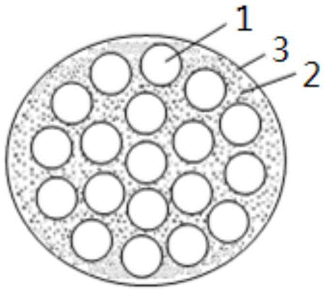
[0085] (1) The components in the gas-liquid mixer are as follows image 3 The membrane tube shown (commercially purchased from Beijing Zhongtianyuan Environmental Engineering Co., Ltd.; the average pore diameter of the pores on the substrate is 100 μm; the average pore diameter of the pores on the porous membrane is 500 nm, and the pores on the porous membrane with a pore diameter in the range of 500-550 nm The proportion of the total pores is 95%); the porous membrane is located on the outer wall of the membrane tube; there are 7 channels evenly distributed, and the inner diameter of each liquid channel is 6mm; the channels on the membrane tube are used as liquid channels, and the membrane tube The space formed by the outer wall and the inner wall of the casing serves as a gas channel, and the filling rate of the membrane tube in the casing is 45%.
[0...
Embodiment 3
[0090] The coal direct liquefied oil was hydrotreated by the same method as in Example 1, the differences are as follows.
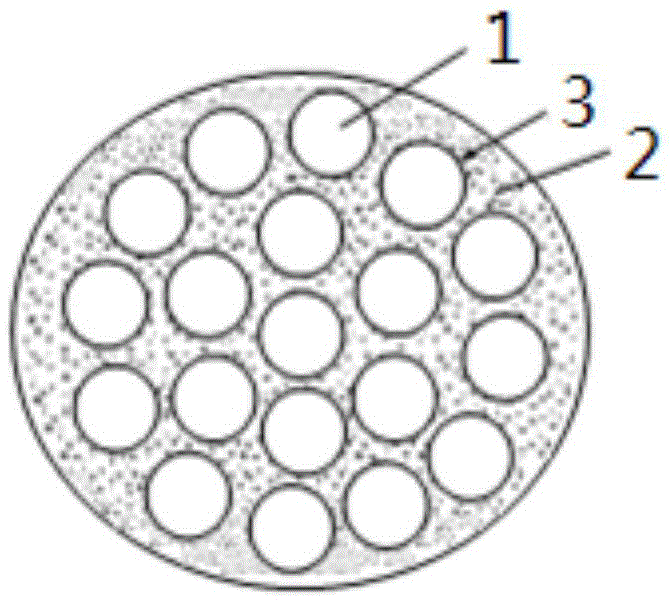
[0091] (1) The components in the gas-liquid mixer are as follows figure 2 The membrane tube shown (commercially purchased from Beijing Zhongtianyuan Environmental Engineering Co., Ltd.; the average pore diameter of the pores on the substrate is 100 μm; the average pore diameter of the pores on the porous membrane is 250 nm, and the pores on the porous membrane with a pore diameter in the range of 250-260 nm The proportion of the total pores is 95%); the porous membrane is located on the inner wall of the membrane tube; there are 7 channels evenly distributed, and the inner diameter of each liquid channel is 6mm; the channel on the membrane tube is used as a liquid channel, and the membrane tube The space formed by the outer wall and the inner wall of the casing serves as a gas channel, and the filling rate of the membrane tube in the casing is 50%.
[0...
PUM
| Property | Measurement | Unit |
|---|---|---|
| Average pore size | aaaaa | aaaaa |
| Average pore size | aaaaa | aaaaa |
| Average pore size | aaaaa | aaaaa |
Abstract
Description
Claims
Application Information
 - R&D
- Intellectual Property
- Life Sciences
- Materials
- Tech Scout
- Unparalleled Data Quality
- Higher Quality Content
- 60% Fewer Hallucinations
Browse by: Latest US Patents, China's latest patents, Technical Efficacy Thesaurus, Application Domain, Technology Topic, Popular Technical Reports.
© 2025 PatSnap. All rights reserved.Legal|Privacy policy|Modern Slavery Act Transparency Statement|Sitemap|About US| Contact US: help@patsnap.com