High-precision wire electric discharge machining machine

A technology of electric discharge wire and cutting machine, applied in the direction of electrode manufacturing, electric processing equipment, metal processing equipment, etc., can solve the problem of affecting the fineness of cutting products and the smoothness of cutting, the long distance from the wire drum to the processing center, and the cutting of molybdenum wire The problems such as the thinning of wire diameter can be solved, and the effect of improving operation efficiency, stable operation and improving quality can be achieved.

Inactive Publication Date: 2015-09-30
淮安凯德数控科技有限公司 +1
View PDF9 Cites 1 Cited by
  • Summary
  • Abstract
  • Description
  • Claims
  • Application Information

AI Technical Summary

Problems solved by technology

However, the vibration generated during the operation of the motor will also drive the wire drum to vibrate; the wire drum always moves left and right, the tangential direction of the wire drum is the same as the output direction of the molybdenum wire, and the molybdenum wire from the wire drum to the working area will present a parabola The radian, resulting in unilateral loose wire, the distance from the wire drum to the processing center is relatively long, the results achieved in the above aspects will affect the fineness of the line output cutting products and the smoothness of cutting
[0004] In addition, wire electric discharge processing accumulates with long-term use. On the one hand, there is loss of molybdenum wire cutting wire, which causes the diameter to become thinner. On the other hand, the length of molybdenum wire cutting wire becomes longer with repeated use, and the cutting products The molybdenum wire will cause slack. Some of the existing machine-installed wire tightening devices use the principle of a heavy hammer to achieve the effect of tightening the wire by manually pulling the guide wheel, and some use the principle of a spring to achieve the effect of tightening the wire, but the output force is not stable enough. , insufficient output

Method used


Image

  • High-precision wire electric discharge machining machine
  • High-precision wire electric discharge machining machine
  • High-precision wire electric discharge machining machine

Examples


Embodiment Construction

[0021] The present invention is further elaborated below in conjunction with accompanying drawing.

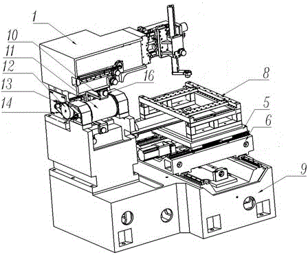
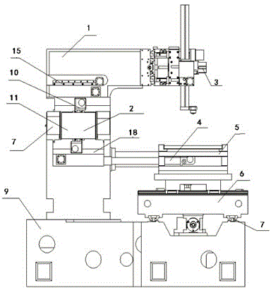
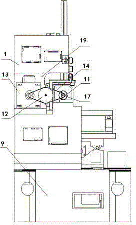
[0022] Such as figure 1 , figure 2 and image 3 As shown, a high-precision wire electric discharge machine includes a bed 9, a wire transport mechanism, a wire frame, a workbench, machine tool electrical appliances and several parts of a numerical control system, wherein the wire transport mechanism includes a wire transport motor 13, a wire storage Tube 11, screw mandrel pair, synchronous wheel 12 and synchronous belt 14, wire transport motor 13 drives storage silk tube 11 to do rotary motion, drives synchronous wheel 12 to rotate by synchronous belt 14 simultaneously.

[0023] The wire frame includes a column 1 fixed on the bed 9 and an upper arm 3 connected with the column 1, a lower arm 4 and several guide wheels 16, and a cavity 19 is provided in the column 1.

[0024] The workbench 8 includes the upper carriage 5, the lower carriage 6, the carriage motor, the carriage...


PUM


Abstract

The invention discloses a high-precision wire electric discharge machining machine. The high-precision wire electric discharge machining machine comprises a body, a wire-conveying mechanism, a wire stand, a workbench, a machine tool electric appliance, and a numerical control system, a wire-conveying motor and a wire-winding cylinder are separately and independently arranged, the central axes of the motor and the wire-winding cylinder are parallel to each other, a synchronizing wheel is arranged between the wire-conveying motor and the wire-winding cylinder, the wire-conveying motor, the wire-winding cylinder, and the synchronizing wheel are connected via a synchronous belt, and the assembling direction of the wire-winding cylinder is vertical to a cutting work area. According to the high-precision wire electric discharge machining machine, the wire-conveying motor and the wire-winding cylinder are separate independent bodies, the wire-winding cylinder is arranged on the body, the conveying of metal wires is realized via the swing left and right of a wire-arranging frame, and single-side wire loosening is prevented; and compared with the prior art, the high-precision wire electric discharge machining machine is advantaged by stable operation, enough output force, and convenient operation and control etc.

Description

[0001] technical field [0002] The invention relates to a wire electric discharge machine tool, in particular to a high-precision wire electric discharge machine. Background technique [0003] In the existing cutting machine, the motor and the wire drum are connected together. For example, the Chinese patent "Wire Cutting Machine Tool" 200710019393.0 (CN101007363) has a cavity in the column, and a vertical wire storage drum is built in the cavity. And through the bracket, the wire rack, the screw guide rod to realize the wire arranging and unwinding. In addition, the upper supporting plate for conveying wire that needs reciprocating linear motion is omitted, the length of the bed can be reduced by one-fifth, and the cost is reduced. However, the vibration generated during the operation of the motor will also drive the wire drum to vibrate; the wire drum always moves left and right, the tangential direction of the wire drum is the same as the output direction of the molybde...

Claims


Application Information

Patent Timeline
Patent Type & Authority Applications(China)
IPC IPC(8): B23H7/10B23H7/02
CPCB23H7/10B23H7/02
Inventor 潘晓雷
Owner 淮安凯德数控科技有限公司
Why Eureka
Try Eureka