Film forming device and method

A film-forming device and film-forming technology, applied in ion implantation plating, gaseous chemical plating, coating, etc., can solve the problems of thermal deformation and low heat resistance of base materials, and achieve simple structure and high film-forming efficiency Effect

Active Publication Date: 2015-09-30
SCREEN HLDG CO LTD
View PDF7 Cites 4 Cited by
  • Summary
  • Abstract
  • Description
  • Claims
  • Application Information

AI Technical Summary

Problems solved by technology

However, when the size of the base material becomes large, the base material is easily thermally deformed by heating, so it is difficult to adopt means such as improving film formation efficiency by heating.
In addition, this method cannot be used when the heat resistance of the base material is low.

Method used


Image

  • Film forming device and method
  • Film forming device and method
  • Film forming device and method

Examples


no. 1 approach >

[0095]

[0096]

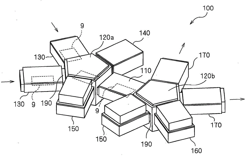
[0097] while referring to figure 1 , the configuration of the plasma processing apparatus 100 will be described. figure 1 is a diagram schematically showing a schematic configuration of the plasma processing apparatus 100 .

[0098] The plasma processing apparatus 100 has a structure in which a set of chambers 130 to 170 are connected in clusters so as to respectively surround two transfer chambers 120 a and 120 b connected via a transfer chamber 110 .

[0099] Specifically, two load-lock chambers (load-lock chambers)) 130, 130, a pre-processing chamber 140, and a film-forming chamber are disposed around a transfer chamber (first transfer chamber) 120a. Room 150. In addition, a film-forming chamber 150, a post-processing chamber 160, and two unload-lock chambers (unload-lock chamber) 170, 170. In addition, the number and layout of the chambers 110 to 170 are not limited to those illustrated in the drawings. For example, the number of the chambers 110...

no. 2 approach >

[0173]

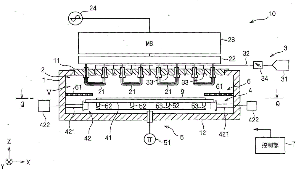
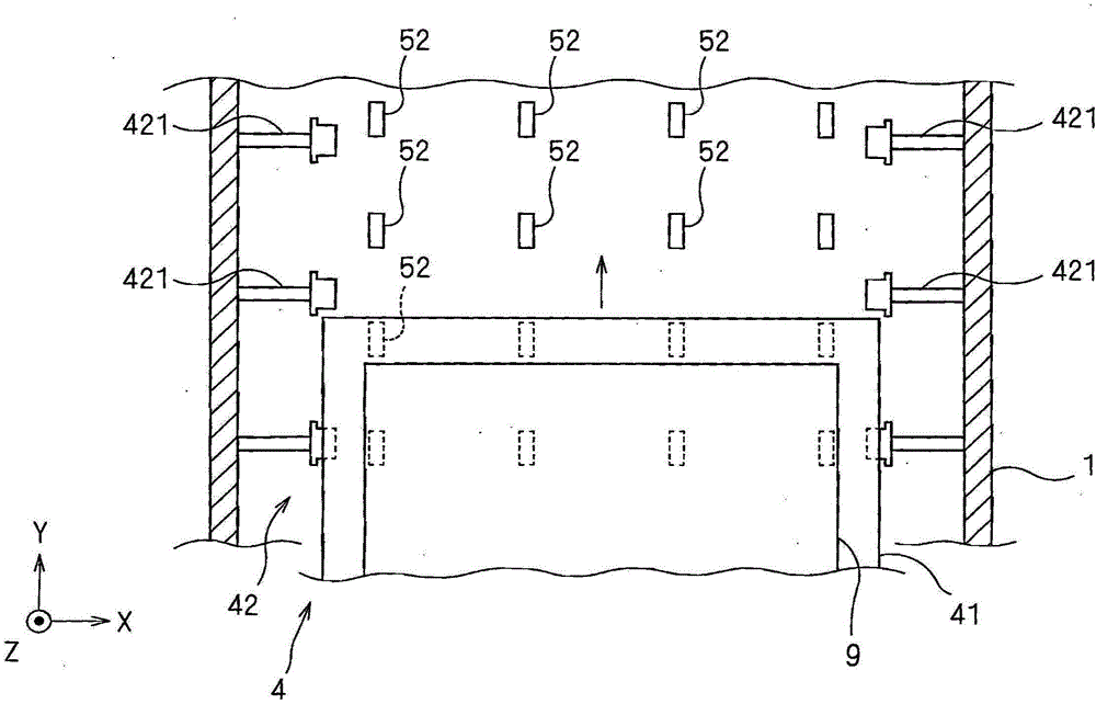
[0174] while referring to Figure 10 to Figure 12 , the film forming apparatus 10a of the second embodiment will be described. Figure 10 It is a side sectional view schematically showing the structure of the film formation apparatus 10a. Figure 11 , Figure 12 It is a figure which shows the arrangement example of the inductive coupling type antenna 21a. In the drawings and the following description, the same structural members as those included in the film formation apparatus 10 according to the first embodiment are assigned the same reference numerals and their descriptions are omitted.

[0175] The film forming apparatus 10a is similar to the film forming apparatus 10 of the first embodiment, and is an apparatus for forming a DLC film on a base material 9 (for example, a glass plate) by plasma CVD. 100.

[0176] The film forming apparatus 10 has: a chamber 1, in which a processing space V is formed; a plasma generation unit 2a, which generates plasma in the ...

no. 3 approach >

[0194]

[0195] while referring to Figure 13 , Figure 14 , the film forming apparatus 10b of the third embodiment will be described. Figure 13 It is a side sectional view schematically showing the structure of the film formation apparatus 10b. Figure 14 It is viewed from the direction of arrow Q Figure 13 top sectional view. In the drawings and the following description, the same structural members as those included in the film formation apparatus 10 according to the first embodiment are assigned the same reference numerals and their descriptions are omitted.

[0196] The film forming apparatus 10b is similar to the film forming apparatus 10 of the first embodiment, and is an apparatus for forming a DLC film on a base material 9 (for example, a glass plate) by plasma CVD. 100.

[0197] The film forming apparatus 10b has: a chamber 1, in which a processing space V is formed; a plasma generation part 2b, which generates plasma in the processing space V; material gas s...


PUM

PropertyMeasurementUnit
Electron densityaaaaaaaaaa

Abstract

The invention provides a film forming device and method capable of improving filming efficiency of a diamond film; the film forming device (10) comprises the following elements: a chamber (1) with a processing room (V); a low inductance coupling antenna (21) arranged in the processing room (V); a high frequency power supply portion (24) intermittently supplying power to the inductance coupling antenna (21); an air supply portion (3) supplying hydrocarbon air to the processing room (V); a relative mobile portion (4) enabling a substrate material (9), being object material of film formation, to move against the inductance coupling antenna (21); a voltage application portion (5) used for applying cathode voltage to the substrate material (9) when high frequency power is temporally stopped to the inductance coupling antenna (21).

Description

technical field [0001] The present invention relates to a technique for forming a diamond-like carbon (DLC) film. Background technique [0002] The diamond-like carbon film has high hardness and strength (mechanical strength), and is excellent in low wear resistance and wear resistance, so it is widely used in various applications such as hardened coatings. [0003] When forming the diamond-like carbon film, for example, a plasma-enhanced chemical vapor deposition (CVD) method is used. Patent Documents 1 to 3 describe devices for forming a diamond-like carbon film by plasma CVD. [0004] Patent Document 1: Japanese Patent No. 4145361 [0005] Patent Document 2: Japanese Patent No. 4646763 [0006] Patent Document 3: Japanese Patent No. 4704453 [0007] When forming a diamond-like carbon film by plasma CVD, in order to improve film formation efficiency, for example, means of heating a base material to be formed into a film is generally employed. However, when the size of...

Claims


Application Information

Patent Timeline
IPC IPC(8): C23C16/27C23C16/458C23C16/44
CPCC23C14/0611C23C16/505H01L21/02115H01L21/02274
Inventor 中岛直人羽田浩二吉野裕文
Owner SCREEN HLDG CO LTD
Why Eureka
Try Eureka