Immersion liquid limiting mechanism

A technology of limiting mechanism and immersion liquid, which is applied in the direction of photolithography exposure device, microlithography exposure equipment, etc., to avoid excessive impact force, solve the problem of droplet splashing, and the effect of large repulsion force

Active Publication Date: 2015-09-30
SHANGHAI MICRO ELECTRONICS EQUIP (GRP) CO LTD
View PDF6 Cites 4 Cited by
  • Summary
  • Abstract
  • Description
  • Claims
  • Application Information

AI Technical Summary

Problems solved by technology

[0010] The present invention provides a liquid immersion limiting mechanism to sol

Method used


Image

  • Immersion liquid limiting mechanism
  • Immersion liquid limiting mechanism
  • Immersion liquid limiting mechanism

Examples


Embodiment 1

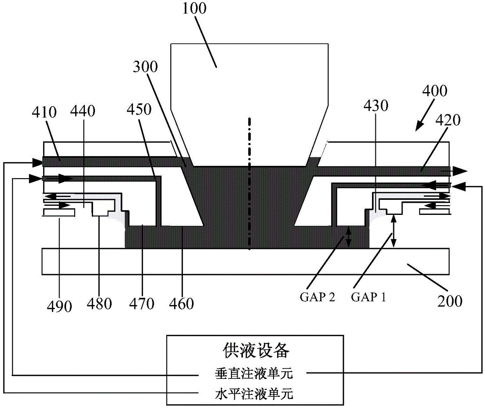
[0062] Preferably, please focus on the reference Figure 7 , the control system of the vertical liquid supply channel 450 includes a sensor 451, a closed-loop control unit 452 and a flow adjustment unit. In this embodiment, the flow adjustment unit uses a magnetic levitation centrifugal pump 453. When in use, the magnetic levitation centrifugal pump 453 can With return channel, such as Figure 7 shown in . Both the sensor 451 and the flow regulating unit are disposed in the vertical liquid supply channel 450 , and the sensor 451 and the flow regulating unit are respectively connected to the closed-loop control unit 452 . Specifically, when the distance between the second plane 470 and the upper surface of the silicon wafer 200 decreases (that is, when there is a risk of collision between the immersion liquid limiting mechanism 400 and the silicon wafer 200 or the workpiece table), the liquid injection resistance of the vertical liquid supply channel 450 ( Load) increases, if...

Embodiment 2

[0064] Preferably, please focus on the reference Figure 8 , the difference between this embodiment and Embodiment 1 is that the flow regulating unit adopts a two-way flow regulating valve 454. When in use, the two-way flow regulating valve 454 can be provided with a return channel, such as Figure 8 shown in . Specifically, the valve body of the two-way flow regulating valve 454 is made of high-purity PFA or PTFE (polytetrafluoroethylene) that is resistant to chemical corrosion and free from pollution such as metals and particles. The contact part of 300 is required to be made of high-purity PFA that is resistant to chemical corrosion and free from pollution such as metals and particles; the sensor 451 collects the flow velocity or pressure of the immersion liquid 300 in the vertical liquid supply channel 450, and feeds back to the closed-loop control unit 452, the closed-loop control unit 452 electronically adjusts the driver connected to the two-way flow regulating valve 4...


PUM

PropertyMeasurementUnit
Widthaaaaaaaaaa
Widthaaaaaaaaaa
Widthaaaaaaaaaa

Abstract

The invention relates to an immersion liquid limiting mechanism. Immersion liquid is limited between a projection objective and a silicon wafer. The immersion liquid limiting mechanism comprises a horizontal liquid supplying passage, a liquid outlet passage, a gas-liquid recovery passage, a gas supplying passage and a vertical liquid supplying passage, wherein the horizontal liquid supplying passage and the liquid outlet passage are horizontally arranged, an outlet of the vertical liquid supplying passage, an outlet of the gas-liquid recovery passage and an outlet of the gas supplying passage are sequentially arranged at the bottom of the immersion liquid limiting mechanism from inside to outside, the horizontal liquid supplying passage and the vertical liquid supplying passage are respectively connected to liquid supplying equipment, the liquid outlet passage and the gas-liquid recovery passage are respectively connected to gas-liquid recovery equipment, the gas supplying passage is connected to gas supplying equipment, and the width of an opening, formed in the bottom of the immersion liquid limiting mechanism, of the gas supplying passage is ten microns. According to the immersion liquid limiting mechanism, the formation of a 'gas knife' structure is avoided through increasing the width of the opening of the gas supplying passage, so that the problem of liquid droplet splashing during edge exposure is solved; through arranging the vertical liquid supplying passage, a repulsive force facing to the bottom of the immersion liquid limiting mechanism is provided at a risk of collision, and thus disturbance is reduced.

Description

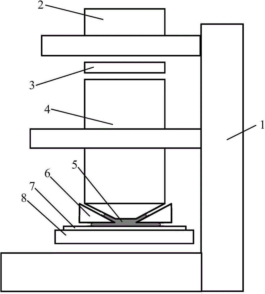
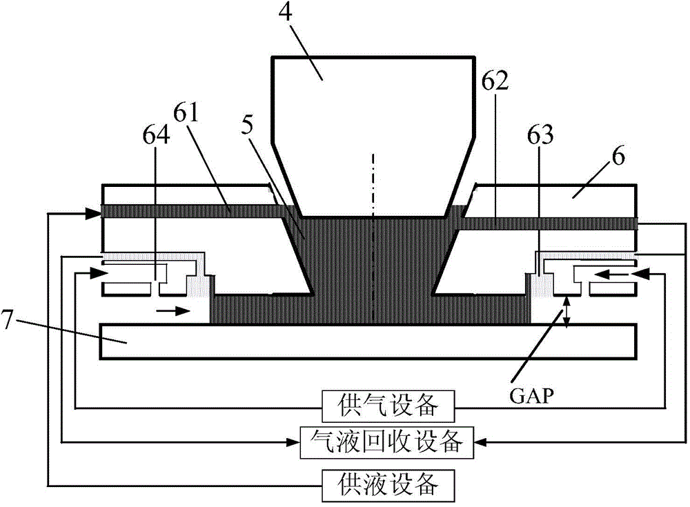
technical field [0001] The invention relates to the field of photolithography equipment, in particular to an immersion liquid limiting mechanism. Background technique [0002] Modern lithography equipment is based on optical lithography, which uses an optical system to accurately project and expose the pattern on the mask onto a substrate (such as a silicon wafer) coated with photoresist. Immersion lithography refers to filling water (or higher refraction immersion liquid) between the exposure lens and the silicon wafer to replace the corresponding air in traditional dry lithography. Since the refractive index of water is larger than that of air, this increases the numerical aperture of the lens group, thereby obtaining a smaller characteristic linewidth. [0003] The structure of the immersion lithography machine is as follows figure 1 As shown, in this device, the illumination system 2, the projection objective lens 4 and the silicon wafer stage 8 are sequentially fixed ...

Claims


Application Information

Patent Timeline
IPC IPC(8): G03F7/20
Inventor 赵丹平张洪博聂宏飞张崇明
Owner SHANGHAI MICRO ELECTRONICS EQUIP (GRP) CO LTD
Why Eureka
Try Eureka