Ultrasonic-electric combined cutting device and method for SiC single crystal wafer.

A cutting method and a technology of a cutting device, which are applied in the field of ultrasonic electric composite cutting device and ultrasonic electric composite cutting, can solve the problems of waste of precious materials, poor surface quality, large deformation of wafers, etc., so as to improve service life, reduce wear, and improve wafer The effect of surface quality

Inactive Publication Date: 2015-11-11
XIAN UNIV OF TECH
View PDF6 Cites 6 Cited by
  • Summary
  • Abstract
  • Description
  • Claims
  • Application Information

AI Technical Summary

Problems solved by technology

[0003] The purpose of the present invention is to provide an ultrasonic electric composite cutting device for SiC single wafers, which solves

Method used


Image

  • Ultrasonic-electric combined cutting device and method for SiC single crystal wafer.

Examples


Example Embodiment

[0038] Example 1:

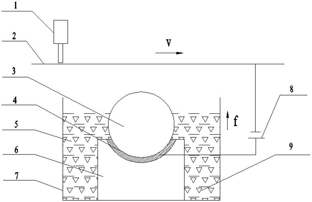
[0039] Step 1. Turn on the DC pulse power supply 8 and the ultrasonic generator 1 and act on the wire saw 2; the voltage of the DC pulse power supply 8 is 0-700V, the voltage pulse width is 6μs-18μs, the peak current is 0-500A, and the current pulse width is 1000μs-3000μs; the amplitude of the ultrasonic generator 1 is 0.1-0.5μm, and the frequency is 20kHz.

[0040] Step 2. The SiC ingot is carried by the machine tool table and fed to the wire saw 2. When the wire saw 2 as the cathode is close to the SiC ingot as the anode, under the action of the DC pulse power supply 8, the wire saw 2 and the SiC ingot The medium between the crystal rods forms a discharge channel, and the instantaneous high temperature in the discharge channel makes the SiC crystal rod as the anode melt and gasify at the discharge, thereby removing the SiC crystal rod material; at the same time, the wire saw 2 is in the ultrasonic generator 1 Under the action of the electrolyte 5, the di...

Example Embodiment

[0042] Example 2:

[0043] Step 1. Turn on the DC pulse power supply 8 and the ultrasonic generator 1 and act on the wire saw 2; the voltage of the DC pulse power supply 8 is 0-700V, the voltage pulse width is 6μs-18μs, the peak current is 0-500A, and the current pulse width is 1000μs-3000μs; the amplitude of the ultrasonic generator 1 is 0.1-0.5μm, and the frequency is 20kHz.

[0044] Step 2. The SiC ingot is carried by the machine tool table and fed to the wire saw 2. When the wire saw 2 as the cathode is close to the SiC ingot as the anode, under the action of the DC pulse power supply 8, the wire saw 2 and the SiC ingot The medium between the crystal rods forms a discharge channel, and the instantaneous high temperature in the discharge channel makes the SiC crystal rod as the anode melt and gasify at the discharge, thereby removing the SiC crystal rod material; at the same time, the wire saw 2 is in the ultrasonic generator 1 Under the action of the electrolyte 5, the di...

Example Embodiment

[0046] Example 3:

[0047] Step 1. Turn on the DC pulse power supply 8 and the ultrasonic generator 1 and act on the wire saw 2; the voltage of the DC pulse power supply 8 is 0-700V, the voltage pulse width is 6μs-18μs, the peak current is 0-500A, and the current pulse width is 1000μs-3000μs; the amplitude of the ultrasonic generator 1 is 0.1-0.5μm, and the frequency is 20kHz.

[0048] Step 2. The SiC ingot is carried by the machine tool table and fed to the wire saw 2. When the wire saw 2 as the cathode is close to the SiC ingot as the anode, under the action of the DC pulse power supply 8, the wire saw 2 and the SiC ingot The medium between the crystal rods forms a discharge channel, and the instantaneous high temperature in the discharge channel makes the SiC crystal rod as the anode melt and gasify at the discharge, thereby removing the SiC crystal rod material; at the same time, the wire saw 2 is in the ultrasonic generator 1 Under the action of the electrolyte 5, the di...


PUM

PropertyMeasurementUnit
Diameteraaaaaaaaaa

Abstract

The invention discloses an ultrasonic-electric combined cutting device for a SiC single crystal wafer. The ultrasonic-electric combined cutting device comprises a glass groove. The glass groove is formed in a machine tool clamp. The bottom in the glass groove is fixedly connected with a resin base. The resin base is provided with a SiC crystal bar. A scroll saw is arranged above the glass groove. An ultrasonic generator is arranged above the scroll saw. The scroll saw is connected with the negative electrode of a direct-current pulse power source to serve as the cathode electrode. The SiC crystal bar is connected with a positive electrode of the direct-current pulse power source to serve as the anode electrode. An electrolytic solution is arranged in the glass groove, and the SiC crystal bar is soaked in the electrolytic solution. Diamond particles are dispersed in the electrolytic solution. The invention further discloses an ultrasonic-electric combined cutting method for the SiC single crystal wafer. According to the ultrasonic-electric combined cutting device and method for the SiC single crystal wafer, through an ultrasonic vibration machining and electrochemical machining combined method, the finished product machining time of the SiC single crystal wafer is shortened, the material removal rate is increased, wafer surface quality is improved, wear of the diamond scroll saw is lowered, waste caused by direct cutting of the scroll saw for precious hard and brittle materials is lowered, and the service life of the cutting device is prolonged.

Description

technical field [0001] The invention belongs to the technical field of non-good conductor processing methods, in particular to an ultrasonic-electric composite cutting device for a SiC single wafer, and also relates to an ultrasonic-electric composite cutting method for a SiC single wafer. Background technique [0002] With the development of technology, SiC, as a third-generation semiconductor material, is more and more widely used in the power device and IC industry. However, due to its high hardness and brittleness, cutting and subsequent processing become the bottleneck of the device manufacturing process. The processing procedure of SiC in the prior art is: cutting into pieces → grinding wafer → polishing wafer, wherein the cutting part occupies about 50% of the entire workload. Ordinary cutting uses a diamond wire saw for cutting. This method has the following problems: 1. Physical cutting, serious deformation of the wafer, large TTV (total thickness variation), and th...

Claims


Application Information

Patent Timeline
IPC IPC(8): B23H5/02B23H7/38
Inventor 李淑娟麻高领黄虎
Owner XIAN UNIV OF TECH
Why Eureka
Try Eureka