Sludge low-temperature waste heat drier

A low-temperature waste heat, drying machine technology, applied in the direction of dehydration/drying/concentrating sludge treatment, etc., can solve the problems of large maintenance, reduce oxygen content, complex drying process, etc., achieve long service life, inhibit volatilization, The effect of fewer wearing parts

Inactive Publication Date: 2015-11-11
石曾矿
View PDF5 Cites 2 Cited by
  • Summary
  • Abstract
  • Description
  • Claims
  • Application Information

AI Technical Summary

Problems solved by technology

[0004] (1) High energy consumption. Drying is a process of net energy consumption. Using steam or heat transfer oil as a heat source requires a large amount of petrochemical energy (coal, fuel oil, gas, electric heating, etc.), and energy consumption usually accounts for 10% of the total processing cost. More than 80%; the existing drying equipment adopts the heating and dehumidification method, and the energy utilization rate is low; the steam consumption per ton of water evaporated is about 1.5 tons, and the power consumption is about 70kw.h;
[0005] (2) Existing high-temperature flue gas waste heat drying has high drying temperature, large amount of dust, and difficult disposal of exhaust gas;
[0006] (3) There is a safety risk, and there is a safety risk if the drying temperature is above 100°C. In order to avoid explosion, the sludge drying usually needs to reduce the oxygen content by adding nitrogen;
[0007] (4) It is not environmentally friendly, emits a large amount of odor, and needs to build a responsible tail gas treatment system; the working environment of the drying workshop is poor; the heating source of the drying process uses a boiler, which also emits a large amount of tail gas, and there is a problem of secondary sludge;
[0008] (5) The drying process is complicated, there are sticky areas, there are many wearing parts of the device, and the maintenance is large

Method used


Image

  • Sludge low-temperature waste heat drier
  • Sludge low-temperature waste heat drier
  • Sludge low-temperature waste heat drier

Examples


Embodiment Construction

[0036] The present invention will be described in detail below in conjunction with the accompanying drawings and specific embodiments.

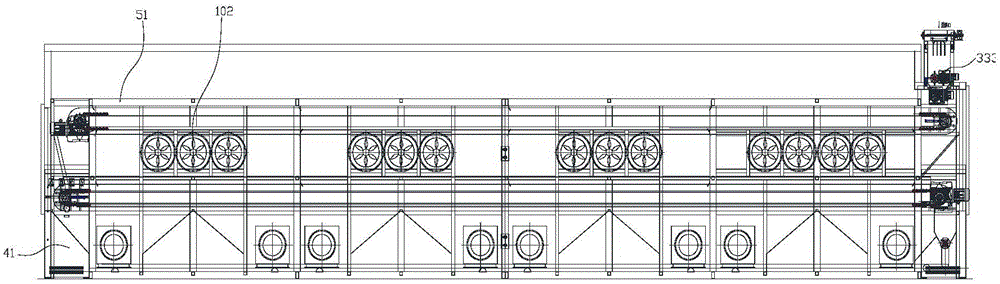
[0037] Sludge low temperature waste heat drying machine, such as figure 1 with Figure 5 As shown, it includes several low-temperature waste heat drying units. According to the needs, several low-temperature waste heat drying units are spliced ​​together to form an overall production line. This is flexible assembly, and the corresponding number of units can be selected according to needs, which is convenient for future expansion and easy transportation.

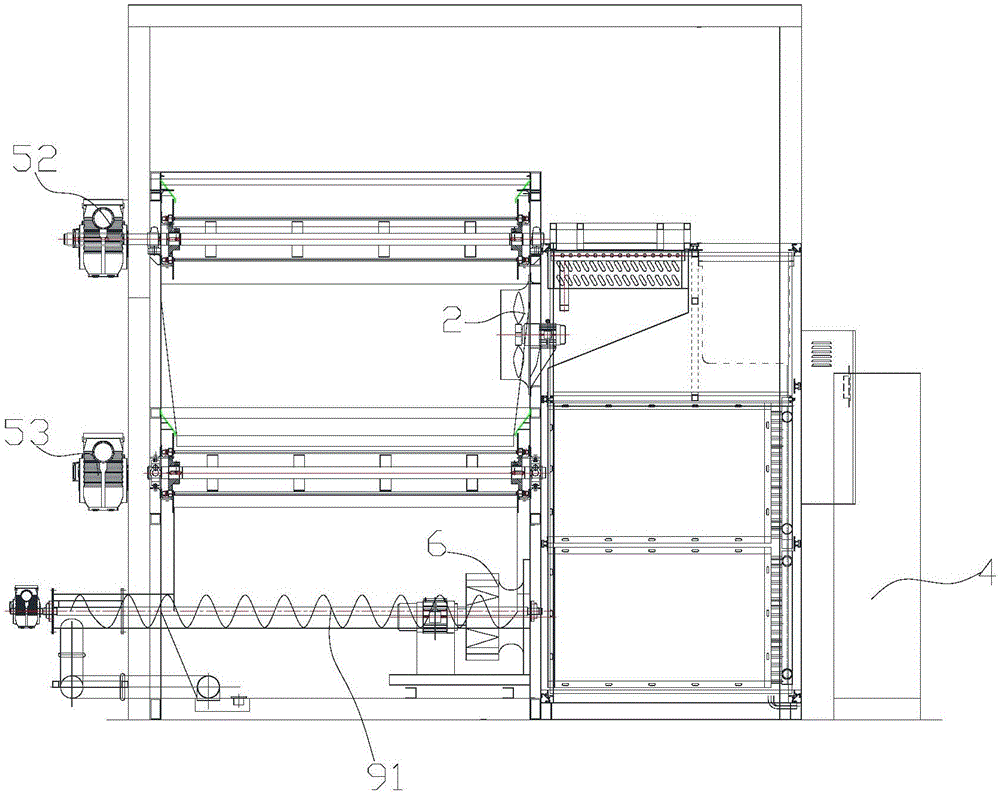
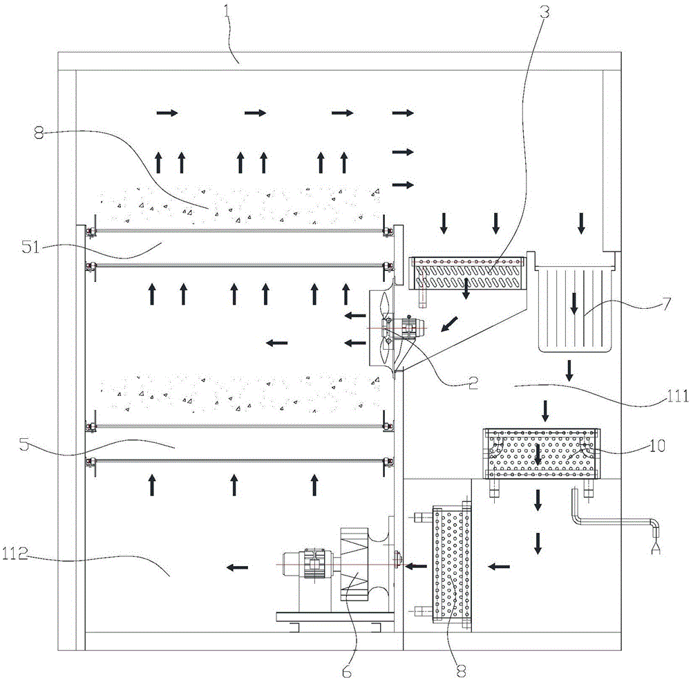
[0038] The low-temperature waste heat drying unit is as Figure 2-4 As shown, it includes a frame 1, the frame 1 is provided with a drying area 112 and a functional area 111, and a baffle is arranged between the drying area 112 and the functional area 11, and between the drying area 112 and the functional area 111 A blower fan 6 and an air return port arranged at the upper end are arranged...


PUM

PropertyMeasurementUnit
thicknessaaaaaaaaaa

Abstract

The invention discloses a sludge low-temperature waste heat drier which comprises a plurality of low-temperature waste heat drying units, wherein the low-temperature waste heat drying units are spliced together; drying zones in the low-temperature waste heat drying units are communicated into an integral body; a mesh belt for drying the material is arranged in each drying zone; the initial end of the uppermost mesh belt is provided with a material inlet; the outlet of the bottommost mesh belt is provided with a material outlet; and the material outlet is provided with a material output device. The sludge low-temperature waste heat drier has the advantages of favorable energy saving property, high safety, favorable environment friendliness and no exhaust discharge, and does not need any stink treatment system.

Description

【Technical field】 [0001] The invention relates to the field of drying equipment, in particular to a sludge low-temperature waste heat drying machine. 【Background technique】 [0002] At present, the commonly used drying systems are mainly carried out by direct or indirect heating, and the drying process is mainly based on a drying temperature greater than 150°C. Existing dryers use petrochemical energy (coal, fuel oil, gas) as fuel for heating. [0003] In general, the existing sludge dryers have the following deficiencies: [0004] (1) High energy consumption. Drying is a process of net energy consumption. Using steam or heat transfer oil as a heat source requires a large amount of petrochemical energy (coal, fuel oil, gas, electric heating, etc.), and energy consumption usually accounts for 10% of the total processing cost. More than 80%; the existing drying equipment adopts the heating and dehumidification method, and the energy utilization rate is low; the steam consump...

Claims


Application Information

Patent Timeline
Patent Type & Authority Applications(China)
IPC IPC(8): C02F11/12
Inventor 石曾矿
Owner 石曾矿
Why Eureka
Try Eureka